
Rotor position measuring system and method of permanent magnetic motor

A rotor position, permanent magnet motor technology, applied in the direction of electronic commutator, etc., can solve the problems of low reliability, low hardware circuit integration, high cost, etc., and achieve the effect of improving reliability, reducing cost, and compressing circuit board space

Inactive Publication Date: 2018-04-20
HUIZHOU BLUEWAY ELECTRONICS
View PDF5 Cites 1 Cited by
  • Summary
  • Abstract
  • Description
  • Claims
  • Application Information

AI Technical Summary

Problems solved by technology

[0004] The invention provides a measurement system for the rotor position of a permanent magnet motor. The technical problem to be solved is that in the prior art, a hardware circuit is used to complete the differential of the phase current, and a hardware voltage comparator is used to compare the signal with the corresponding divided voltage signal The method of determining the rotor position of the permanent magnet motor has low hardware circuit integration, low reliability and high cost

Method used


Image

  • Rotor position measuring system and method of permanent magnetic motor
  • Rotor position measuring system and method of permanent magnetic motor
  • Rotor position measuring system and method of permanent magnetic motor

Examples


Embodiment Construction

[0032] The implementation of the present invention will be explained in detail below in conjunction with the accompanying drawings. The examples are given for illustrative purposes only, and should not be understood as limiting the present invention, including the selection and value of the components and the accompanying drawings. Examples are for reference and illustration only, and do not constitute a limitation to the patent protection scope of the present invention, because many changes can be made to the present invention without departing from the spirit and scope of the present invention.

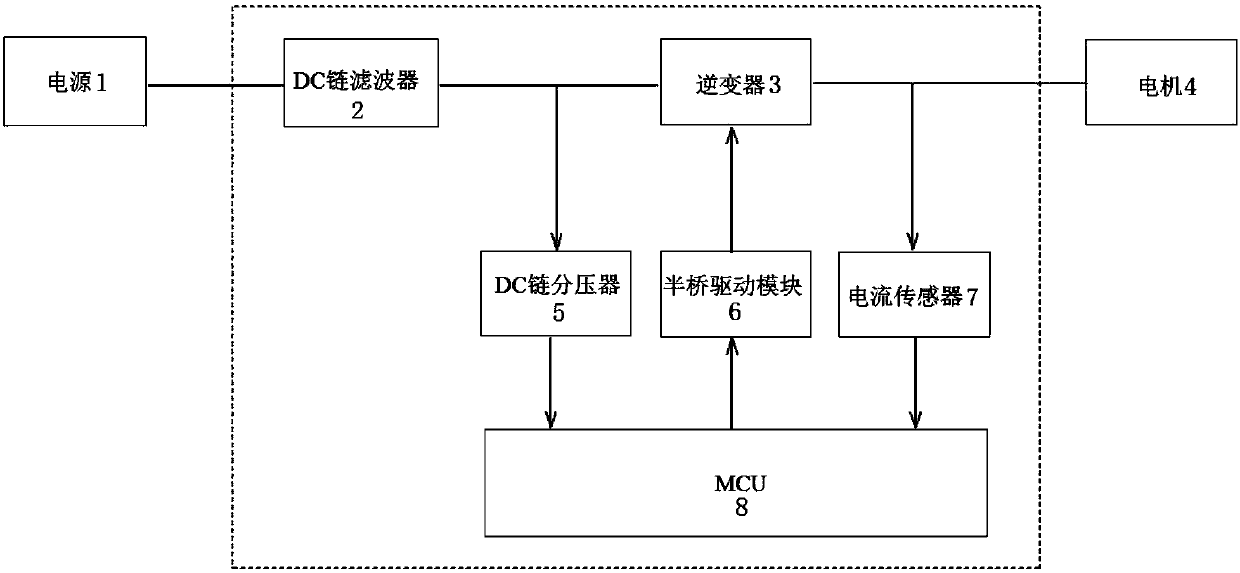
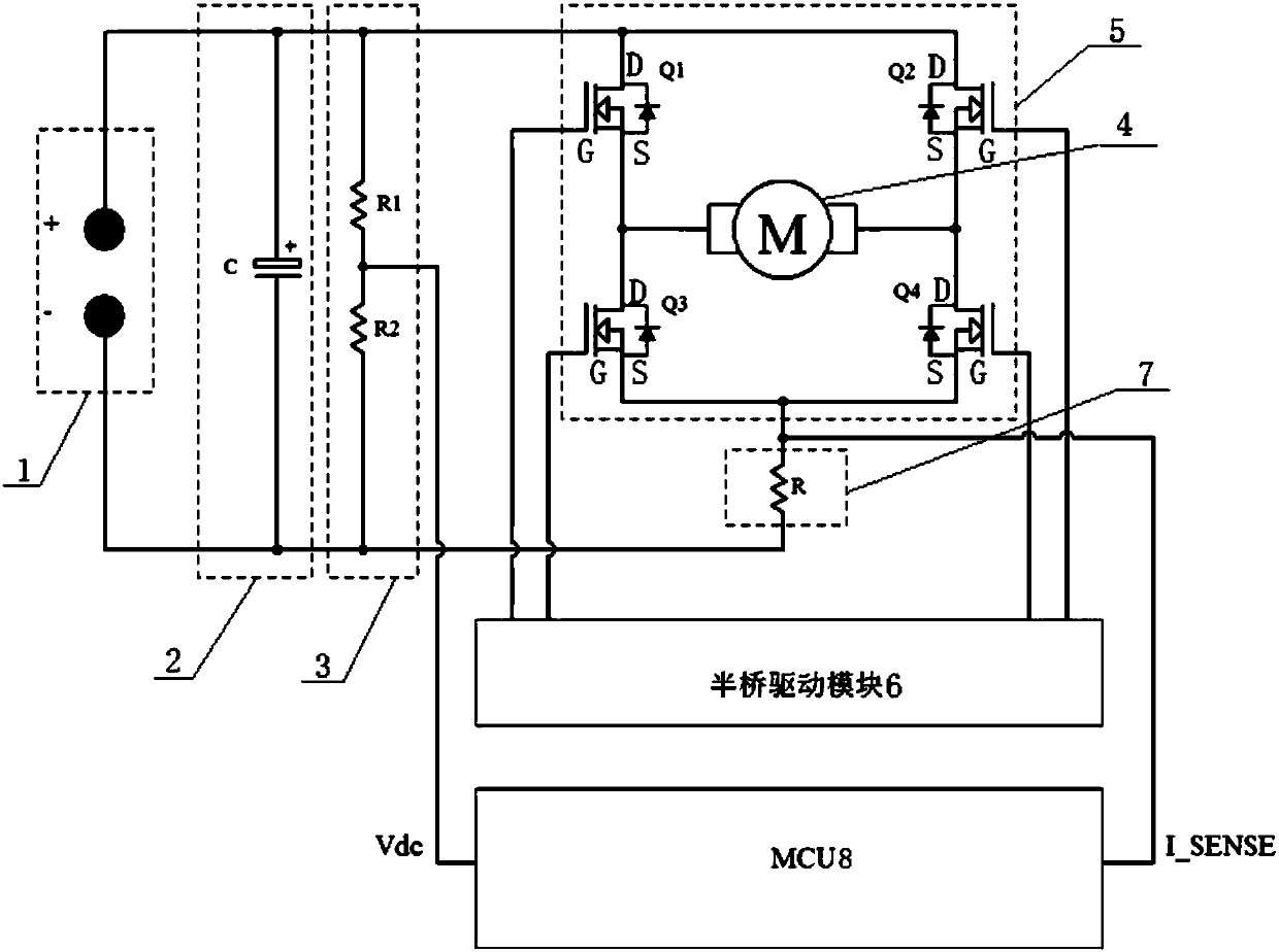
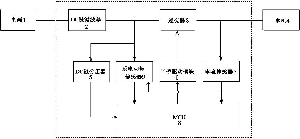
[0033] A module structure diagram of a measurement system for the rotor position of a permanent magnet motor provided in an embodiment of the present invention, as shown in figure 1 As shown, in this embodiment, the measurement system for the rotor position of a permanent magnet motor is provided with a power supply 1, a DC filter 2, an inverter 3, a motor 4, a DC link voltage divide...


PUM


Abstract

The invention discloses a rotor position measuring system and method of permanent magnetic motor, and relates to the technical field of rotors of permanent magnetic motors. The system is provided witha power supply, a DC filter, an inverter, a motor, a DC link voltage divider, a half-bridge driving module, a current sensor and an MCU, the DC filter and the inverter are connected in series sequentially between the power supply and the motor, the DC link voltage divider is connected between the filtering output end of the DC filter and the voltage sampling input end of the MCU, the half-bridgedriving module is connected between the control output end of the MCU and the control input end of the inverter, and the current sensor is connected between the signal output end of the inverter and the current sampling input end of the MCU. Compared with present schemes, a back electromotive force sensor is omitted in the aspect of hardware, the space of a circuit board is reduced effectively, the reliability of application products which use the system and method is improved to certain extent, and the cost is reduced.

Description

technical field [0001] The invention relates to the technical field of permanent magnet motor rotors, in particular to a measuring system and method for the position of a permanent magnet motor rotor. Background technique [0002] With the increasing development of the motor industry, brushless DC motors have been widely used in many fields such as washing machines. It has the advantages of good speed regulation performance, small size, long life and high efficiency. However, the start-up and rotor positioning control of the brushless DC motor without Hall sensors has always been a difficult problem in the industry, which seriously restricts the scope of application of the motor. [0003] In the prior art, Dyson Technology Co., Ltd. used a hardware circuit (mainly composed of a DC link filter, a DC link voltage divider) in the invention "Method for Determining the Rotor Position of a Permanent Magnet Motor" (Patent No. CN104285369A) on a brushless DC motor. Inverter, invert...

Claims


Application Information

Patent Timeline
IPC IPC(8): H02P6/18
CPCH02P6/18
Inventor 苏炳坤刘辉朱立湘尹志明林军
Owner HUIZHOU BLUEWAY ELECTRONICS
Learn More