
Synchronous dual-frequency circuit board radiating antenna

A radiating antenna and circuit board technology, applied in the field of communication, can solve the problems of unsuitable frequency interval and large frequency interval, etc., and achieve the effect of saving circuit board space and reducing antenna cost

Active Publication Date: 2013-12-11
深圳汉阳天线设计有限公司
View PDF3 Cites 8 Cited by
  • Summary
  • Abstract
  • Description
  • Claims
  • Application Information

AI Technical Summary

Problems solved by technology

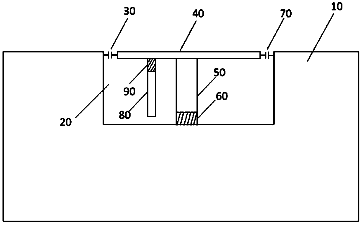
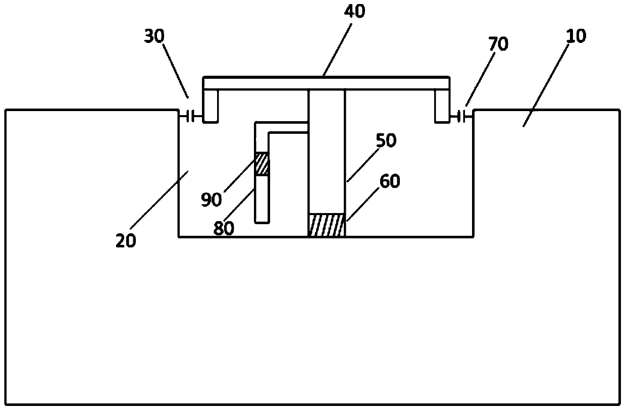
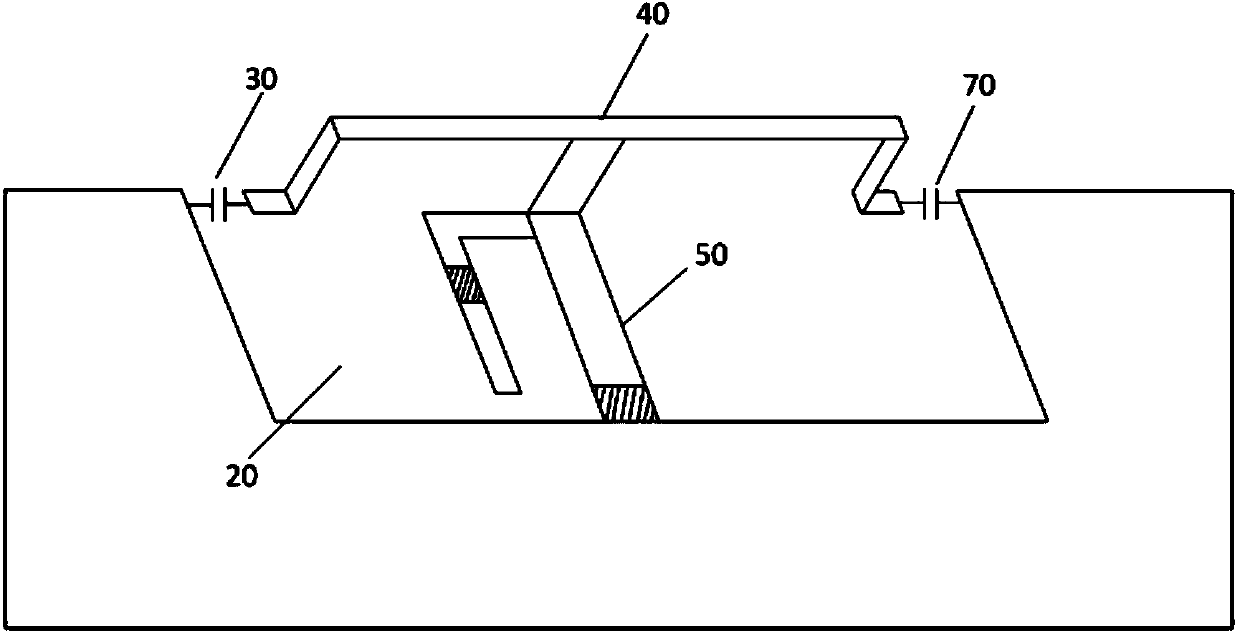
[0004] The invention proposes a synchronous dual-frequency circuit board radiation antenna, which solves the problem that the frequency interval between the two communication frequency bands of the existing circuit board radiation antenna is relatively large and cannot be applied to dual-frequency frequency bands with small frequency intervals

Method used


Image

  • Synchronous dual-frequency circuit board radiating antenna
  • Synchronous dual-frequency circuit board radiating antenna
  • Synchronous dual-frequency circuit board radiating antenna

Examples


Embodiment Construction

[0022] The following will clearly and completely describe the technical solutions in the embodiments of the present invention with reference to the accompanying drawings in the embodiments of the present invention. Obviously, the described embodiments are only some, not all, embodiments of the present invention. Based on the embodiments of the present invention, all other embodiments obtained by persons of ordinary skill in the art without making creative efforts belong to the protection scope of the present invention.

[0023] The existing circuit board radiation antenna is only suitable for the case where the resonance frequency of the high frequency is more than twice the resonance frequency of the low frequency. In order to solve various drawbacks of the prior art, the present invention proposes a synchronous dual-frequency circuit board radiation antenna , using a clearance area on the circuit board to simultaneously form two different circular currents, that is, two diffe...


PUM


Abstract

The invention provides a synchronous dual-frequency circuit board radiating antenna. The synchronous dual-frequency circuit board radiating antenna comprises an earth wire, wherein the earth wire is paved on a printed circuit board of a mobile phone and provided with a clearance area; two ring current films are arranged in the clearance area; the first ring current film comprises a first capacitor, a connecting line and an earthing line; the second ring current film comprises a second capacitor, a connecting line and an earthing line; a feeder line is further arranged in the clearance area, one end of the feeder line is connected to a signal source, and the other end of the feeder line is connected to the connecting lines through second elements. The synchronous dual-frequency circuit board radiating antenna stimulates the circuit board to produce a radiation effect between a GPS frequency band and a WiFi frequency band which have smaller frequency space (about 900MHz) at the same time, and thus the space of the circuit board and the cost of the antenna are saved again on the basis that radiative performance of the circuit board is kept.

Description

technical field [0001] The invention relates to the communication field, in particular to a mobile communication antenna. Background technique [0002] At present, the pace of diversification of mobile phone functions continues to accelerate, ushering in the era of smart phones that integrate entertainment, photography, web surfing, and video calls. Mobile phones have become portable computers that can be put in pockets. The research and development standards of smartphones imperceptibly promote the continuous increase of the integration of modern mobile phones, and the mobile phone market has more and more urgent requirements for antenna miniaturization. However, the size of the antenna directly affects the transmission and reception performance of the signal, that is to say, the smaller the antenna, the lower the transmission and reception performance. Such physical characteristics have erected a seemingly insurmountable barrier in front of antenna R&D engineers. [0003]...

Claims


Application Information

Patent Timeline
IPC IPC(8): H01Q5/01H01Q1/36H01Q1/24H01Q5/10
Inventor 刘扬路欣欣张瑞徐兆杰张顺
Owner 深圳汉阳天线设计有限公司
Learn More