Air conditioner for vehicle

A technology for air-conditioning devices and vehicles, which is applied to air-conditioning systems, vehicle components, applications, etc., and can solve problems such as complex systems and increased number of parts

Active Publication Date: 2018-04-24
HONDA MOTOR CO LTD
View PDF6 Cites 3 Cited by
  • Summary
  • Abstract
  • Description
  • Claims
  • Application Information

AI Technical Summary

Problems solved by technology

Therefore, the number of parts of the vehicle air co...

Method used


Image

  • Air conditioner for vehicle
  • Air conditioner for vehicle
  • Air conditioner for vehicle

Examples


Embodiment Construction

[0034] Hereinafter, embodiments of the present invention will be described with reference to the drawings.

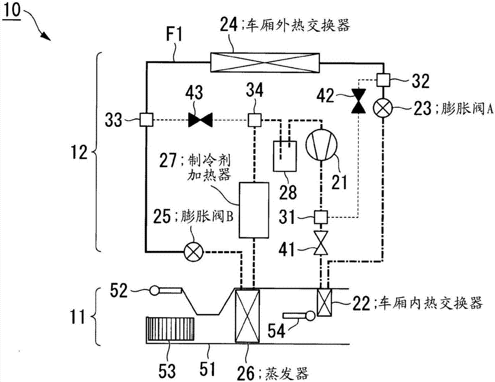
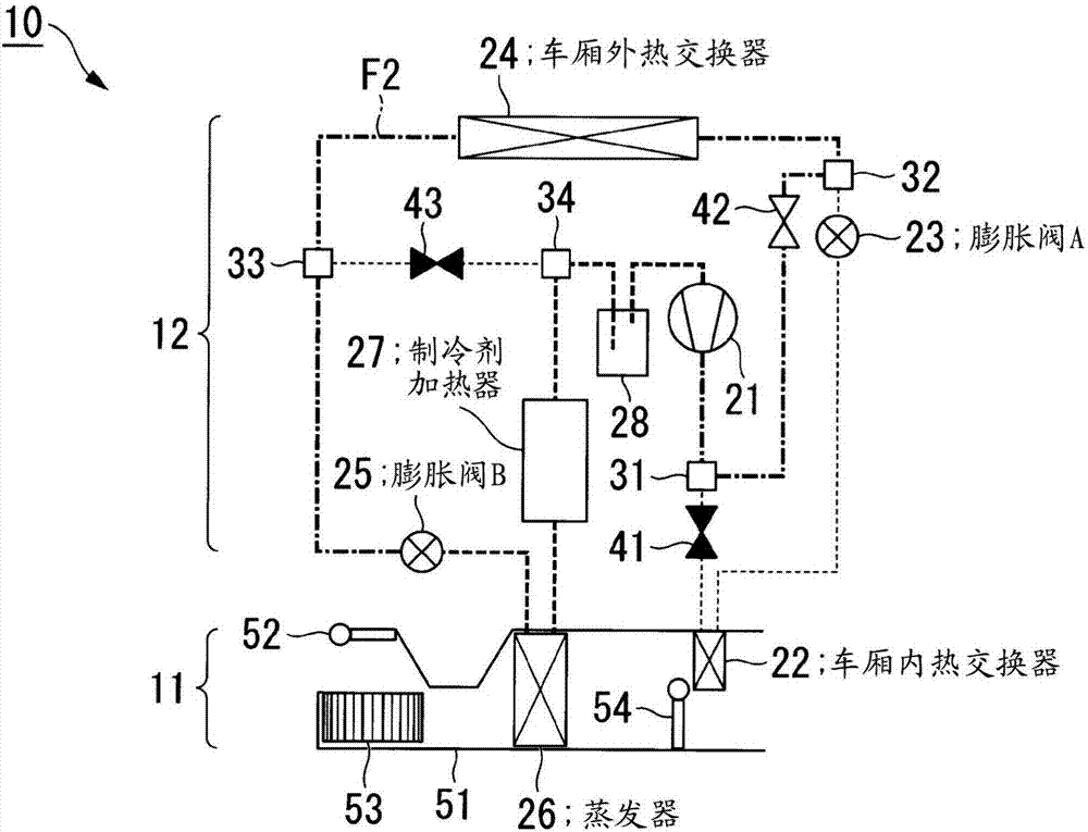
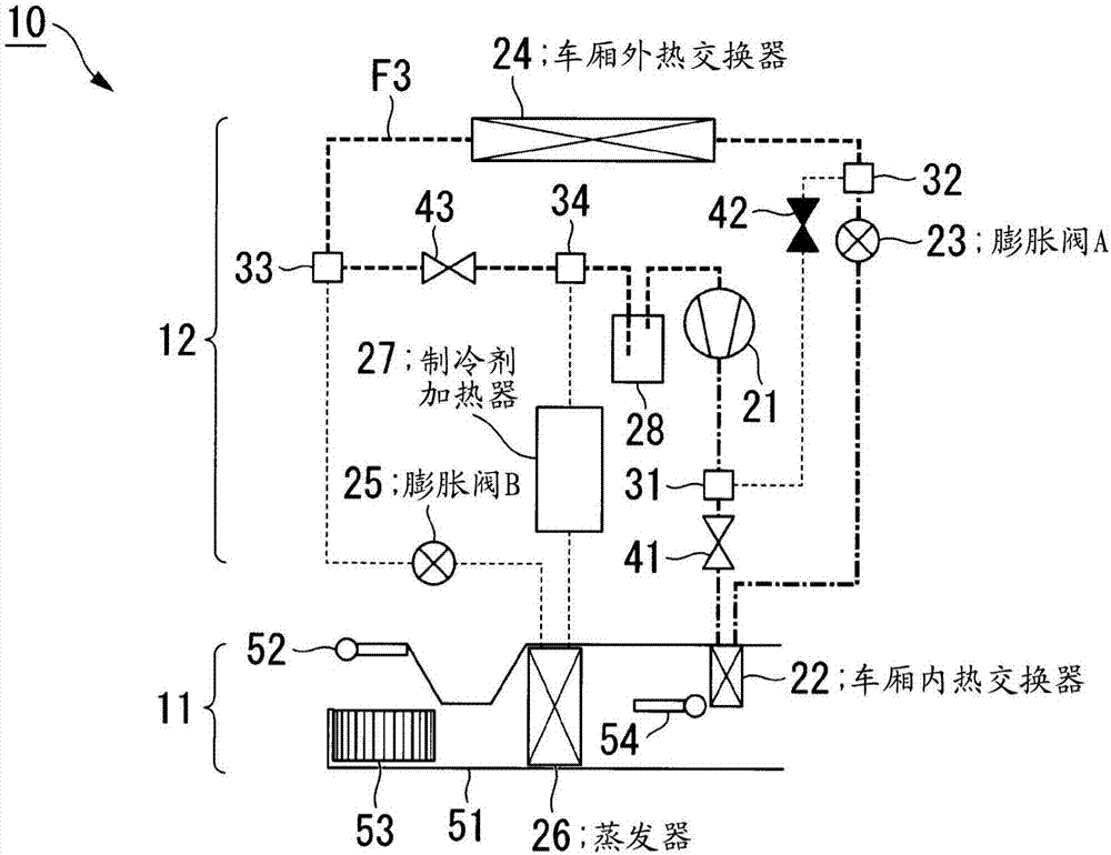
[0035] Figure 1 ~ Figure 3 It is a configuration diagram of the vehicle air conditioner 10 according to the present embodiment. figure 1 It indicates the flow of refrigerant during dehumidification and heating operation. exist figure 1 In , thick lines and dotted lines denote refrigerant flow paths and flow paths where no refrigerant flows, respectively. figure 2 Indicates the flow of refrigerant during cooling operation. image 3 Indicates the flow of refrigerant during heating operation. In addition, the dehumidification and heating operation, the cooling operation, and the heating operation are referred to as a dehumidification and heating mode, a cooling mode, and a heating mode, respectively.

[0036] Vehicle air conditioner 10 includes an air conditioner 11 , a heat pump cycle 12 , and a control unit (not shown). The "vehicle use" in the vehicle air cond...


PUM


Abstract

The invention provides an air conditioner for a vehicle having a simple configuration and capable of controlling temperature in a wide range. In a dehumidification heating operation in which a refrigerant is circulated through a first heat exchanger, a second heat exchanger, an evaporator and a compressor in the order named so as to radiate the heat of the refrigerant into the first heat exchanger, there is provided a refrigerant heating means which heats the refrigerant when an outside air temperature is not higher than a predetermined temperature and when an opening degree of the second expansion valve which expands the refrigerant flowing out from the second heat exchanger is larger than an opening degree of the first expansion valve which expands the refrigerant flowing out from the first heat exchanger.

Description

technical field [0001] The invention relates to a vehicle air conditioner. Background technique [0002] Conventionally, a vehicle air conditioner has been proposed that performs a dehumidification and heating operation using a heat pump cycle (see Patent Document 1). E.g, Figure 13 The illustrated vehicle air conditioner 91 has a compressor 21 , an interior heat exchanger 22 , an expansion valve A23 , an exterior heat exchanger 24 , an expansion valve B25 , and an evaporator 26 as constituent elements. During the dehumidification and heating operation, the refrigerant (refrigerant) circulates in this order in the circuit composed of these components. The evaporator 26 and the indoor heat exchanger 22 are housed in a duct 51 , and the evaporator 26 is arranged upstream of the indoor heat exchanger 22 with respect to the flow direction of conditioned air in the duct 51 . [0003] As a method of adjusting the temperature of the conditioned air, there is known a method of lo...

Claims


Application Information

Patent Timeline
IPC IPC(8): B60H1/32B60H1/00B60H3/02F25B1/00F25B29/00F25B41/04F25B41/06F25B49/02
CPCB60H1/00921B60H1/3204B60H1/3216B60H1/3227B60H3/024F25B1/00F25B29/003F25B49/02B60H2001/00957B60H2001/00949B60H2001/00928F25B2600/2513F25B2600/2519F25B2700/2106F25B2313/02323F25B2313/02321F25B2313/02343F25B41/24F25B41/34F25B5/04F25B6/04F25B2400/01F25B2400/0403F25B2400/0409F25B2400/0411F25B2500/31F25B2600/0253F25B2600/2501F25B41/39Y02B30/70B60H1/00007F24F3/14F24F2003/144F25B13/00F25B39/00
Inventor 角田功
Owner HONDA MOTOR CO LTD
Why Eureka
Try Eureka