Drainage system and method

A drainage system and drainage pipe technology, which is applied in drainage, earthwork drilling, pump control, etc., can solve problems affecting underground production, mine submersion, and large operation randomness, so as to reduce equipment failure rate, reduce running time, reduce The effect of the number of starts

Inactive Publication Date: 2018-04-24
TAIYUAN UNIV OF TECH
View PDF6 Cites 17 Cited by
  • Summary
  • Abstract
  • Description
  • Claims
  • Application Information

AI Technical Summary

Problems solved by technology

Once the underground drainage system fails, it will not only affect the underground production, but even flood the mine, endangering the lives of production workers
[0003] At present, the underground main drainage system can be divided into two categories: manual local control system and automatic control system; among them, the problems of the manual local control system are as follows: ① This method is mainly manual control, so the water level detection The accuracy is not high, the operation is random, and the real-time monitoring of the water inflow and the scientific scheduling of the drainage process cannot be realized
When the water inflow suddenly increases, if the operator fails to detect and deal with it in time, it will lead to major safety accidents; ② Manual operation cannot avoid high-intensity work, especially the operation of gate valves, which has the largest labor load
Although the automatic control system partially solves the problem of the manual local control system, the control function is not perfect, and it is impossible to realize the automatic operation of "unattended" underground and the real-time monitoring and monitoring of the personnel on the well; and the equipment failure rate is relatively high
[0004] Aiming at the problem of the automatic control system, the industry has also proposed many solutions. For example, the publication number is CN10

Method used


Image

  • Drainage system and method
  • Drainage system and method
  • Drainage system and method

Examples


Embodiment 1

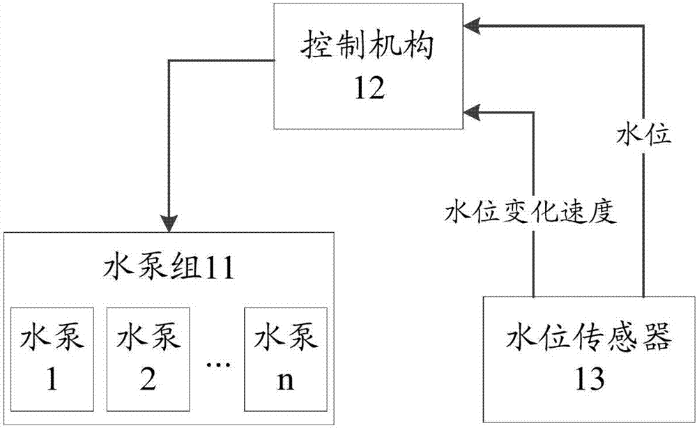
[0050] figure 1 It is a schematic diagram of a drainage system in an embodiment of the present invention, as figure 1 As shown, a drainage system includes a water pump group 11, a control mechanism 12 and a water level sensor 13; wherein,

[0051] The water pump group 11 is used for: draining water according to the instruction of the control mechanism 12, and the water pump group 11 is provided with at least two water pumps, so that it is convenient to alternate between the water pumps and reduce the failure rate of equipment;

[0052] The control mechanism 12 is configured to: when the water level information reaches a preset condition, instruct the water pump group 11 to drain water;

[0053] Here, the water level information includes the water level and the rate of change of the water level. The rate of change of the water level is also referred to as the rate of change of the water level. is a negative value, so that when the water level change rate is large, it means that...

Embodiment 2

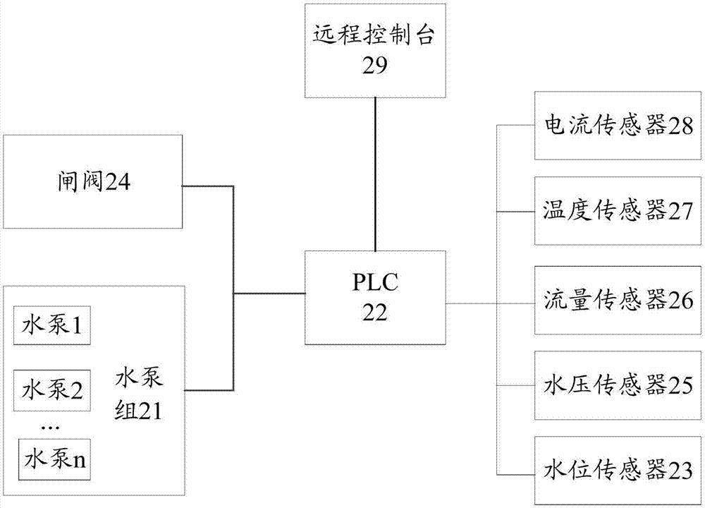
[0057] figure 2 It is a schematic diagram of the second drainage system of the present invention, as figure 2 As shown, a drainage system includes a water pump group 21, PLC22, a water level sensor 23, a gate valve 24, a water pressure sensor 25, a flow sensor 26, a temperature sensor 27, a current sensor 28, a remote console 29 and an on-site operation console; wherein,

[0058] The water pump group 21 is used for: draining water according to the instruction of the PLC22, and the water pump group 21 is provided with at least two water pumps, which facilitates the alternate work between the water pumps and reduces the equipment failure rate;

[0059] The water pumps are all centrifugal pumps, and above the centrifugal pumps are equipped with jet pumps that help the centrifugal pumps to generate negative pressure; specifically, the water pump startup process includes: first start the jet pumps to make the centrifugal pumps generate negative pressure, that is, Vacuum degree, ...

Embodiment 3

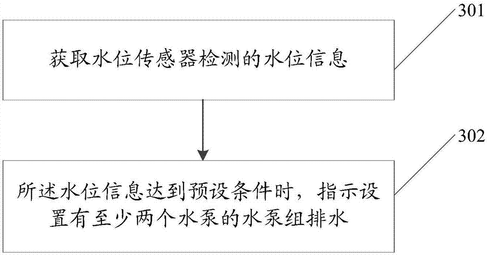
[0098] image 3 It is a schematic diagram of the three drainage methods of the embodiment of the present invention, as image 3 As shown, the method includes:

[0099] Step 301: Obtain the water level information detected by the water level sensor;

[0100] Specifically, the drainage system includes a water pump group, a PLC and a water level sensor, and the PLC obtains water level information through the water level sensor;

[0101] The obtaining of the water level information detected by the water level sensor includes:

[0102] The PLC obtains the water level detected by the water level sensor and the speed of water level change;

[0103] Here, the water level change rate is also called the water level change rate. For the convenience of processing, the water level change rate of the water level increase is defined as a positive value, and the water level change rate of the water level decrease is defined as a negative value. In this way, when the water level change rate...


PUM


Abstract

The invention discloses a drainage system and method. The drainage system comprises a water pump set which is provided with at least two water pumps, a control mechanism for controlling the water pumpset to run, and at least one water level sensor which is used for detecting the water level information, and the water pumps in the water pump set and the water level sensors are all connected with the control mechanism; the water level sensor is used for detecting the water level information and sending the detected water level information to the control mechanism; the control mechanism is usedfor indicating the water pumps in the water pump set to conduct drainage when the water level information satisfies a preset condition. By means of the drainage system and method, when water bursts, water permeation or water gushing accidents break out in a mine, the water pump set in the drainage system can be timely started to conduct drainage, and the occurrence of safety accidents is prevented; meanwhile, through the arrangement of the at least two water pumps, when the drainage amount is not large, the two water pumps take turns to work, the starting frequency of the water pumps is reduced, the running time of the water pumps is shortened, and the equipment fault rate is lowered.

Description

technical field [0001] The invention relates to the technical field of drainage, in particular to a drainage system and method. Background technique [0002] With the high-yield and high-efficiency development of the coal industry, mine safety has become a key factor restricting coal production. The underground drainage system is one of the four major systems in coal mine production. It is responsible for the important task of removing underground water. Whether it can operate normally directly affects the safety of the entire mine production. Once the underground drainage system fails, it will not only affect the underground production, but even flood the mine, endangering the lives of production workers. [0003] At present, the underground main drainage system can be divided into two categories: manual local control system and automatic control system; among them, the problems of the manual local control system are as follows: ① This method is mainly manual control, so t...

Claims


Application Information

Patent Timeline
IPC IPC(8): E21F16/00F04D15/00
Inventor 寇子明寇彦飞高贵军吴娟高鑫宇李志刚
Owner TAIYUAN UNIV OF TECH
Why Eureka
Try Eureka