Engine two-level adjustable valve lift device

A valve lift, adjustable technology, applied in the direction of engine components, machines/engines, valve devices, etc., can solve the problems of poor stability, damage to the groove ejector, poor switching stability, etc., to achieve good stability and improve stability. sexual effect

Active Publication Date: 2018-04-24
GUIZHOU GEELY ENGINE CO LTD +1
View PDF5 Cites 2 Cited by
  • Summary
  • Abstract
  • Description
  • Claims
  • Application Information

AI Technical Summary

Problems solved by technology

However, in the two-stage adjustable and variable gas distribution mechanism of this structure, the grooved ejector rod is controlled by an electromagnetic actuator to insert into the spiral groove. Since the diameter of the grooved ejector rod is basically the same as the groove width of the spiral groove, the groove The precision of the embedding of the grooved ejector rod needs to be very high, otherwise the grooved ejector rod will abut against the cam bushing and cannot be embedded in the spiral groove, which will cause the grooved ejector rod to be ejected, so that the low-speed cam and the high-speed The cam cannot be switched freely, the switching stability is poor, and there is a problem of damage to the grooved ejector rod; and even if the grooved ejector rod is embedded in the spiral groove, due to the rotation of the cam bushing, the grooved ejector rod will collide with the end of the spiral groove The groove wall collides, the groove ejector rod will not return in time, and the groove ejector rod is damaged, so that the low-speed cam and the high-speed cam cannot be switched freely, and the switching stability is poor.

Method used


Image

  • Engine two-level adjustable valve lift device
  • Engine two-level adjustable valve lift device
  • Engine two-level adjustable valve lift device

Examples


Embodiment Construction

[0026] The following are specific embodiments of the present invention and in conjunction with the accompanying drawings, the technical solutions of the present invention are further described, but the present invention is not limited to these embodiments.

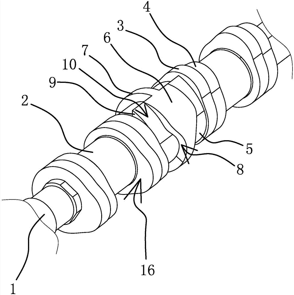
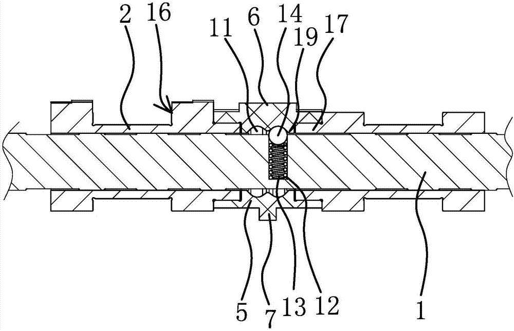
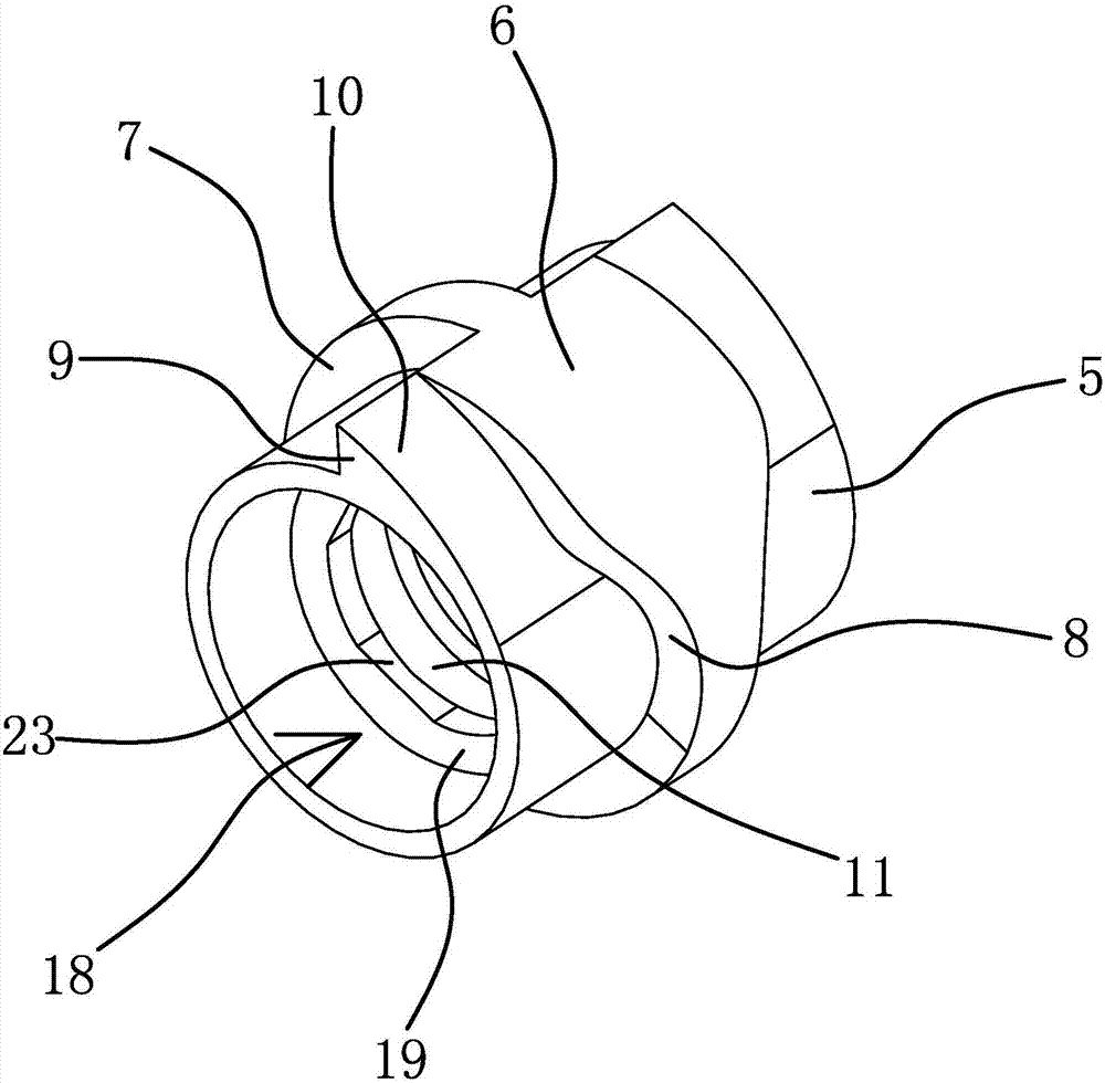
[0027] Such as figure 1 , figure 2 As shown, the two-stage adjustable valve lift device of the engine includes a camshaft 1, a camshaft sleeve 2, a high-speed cam 3, a low-speed cam 4 and an adjustment sleeve 5.

[0028]The outer wall of the camshaft 1 has a protruding abutment ring 20. In this embodiment, the outer wall of the abutment ring 20 has four cut surfaces 21, and the inner wall of the camshaft sleeve 2 is provided with four first The planes 22 , the cutting planes 21 and the first planes 22 are set in one-to-one correspondence. In actual production, the number of the cutting planes 21 can be three or six, and the number of the first planes 22 can also be three or six. The camshaft sleeve 2 is circumferentiall...


PUM


Abstract

The invention provides an engine two-level adjustable valve lift device, and belongs to the technical field of automobiles. The engine two-level adjustable valve lift device solves the problem that anexisting two-level adjustable valve lift device is poor in stability. The engine two-level adjustable valve lift device comprises a cam shaft and cam shaft sleeves, the cam shaft sleeves are positioned outside the cam shaft in the circumferential direction, and each cam shaft sleeve is fixedly connected with a high-speed cam and a low-speed cam. The cam shaft is further sleeved with an adjustingsleeve, the adjusting sleeve is positioned between a pair of cam shaft sleeves in the circumferential direction, and an expansion block arranged in a protruding manner and a contraction strip are arranged at the middle position of the outer side wall of the adjusting sleeve. In the axial direction of the adjusting sleeve, the width of the expansion block is larger than that of the contraction strip, the two side walls of the connecting position of one end of the expansion block and one end of the contraction strip are arc movable profiles, the outer side wall of the adjusting sleeve is furtherprovided with failure blocks, the failure blocks are located on the two sides of the expansion block, and the outer surfaces of the failure blocks are gradually-opened failure profiles. The engine two-level adjustable valve lift device has the beneficial effect of being good in stability.

Description

technical field [0001] The invention belongs to the technical field of automobiles and relates to a two-stage adjustable valve lift device for an engine. Background technique [0002] The gas distribution timing of the automobile engine, that is, the opening and closing time of the valve is not exactly the time when the crank is at the top dead center and the bottom dead center, but advances and delays a certain crankshaft angle respectively to improve the intake and exhaust conditions. Thereby improving the power of the engine. However, when the engine speed is different, the requirements for valve timing are different. If the valve timing stipulated by the cam profile is suitable for high speed, then the performance will not be very good at low speed, and vice versa. The variable valve timing can arrange high-speed and low-speed cams on the valve camshaft, and automatically switch the cams according to the engine speed. [0003] Existing variable gas distribution mechani...

Claims


Application Information

Patent Timeline
Patent Type & Authority Applications(China)
IPC IPC(8): F01L13/00
Inventor 刘胜强肖翔闫小倩周武明刘东赵福成王瑞平
Owner GUIZHOU GEELY ENGINE CO LTD
Why Eureka
Try Eureka