
Glasses box with power supply

A spectacle case and power supply technology, which is applied in the direction of current collectors, electric vehicles, electrical components, etc., can solve the problems of moisture in spectacle lenses and inconvenient operation, and achieve the effects of convenient charging, high safety, and simple operation

Inactive Publication Date: 2018-04-27
伊娃
View PDF8 Cites 2 Cited by
  • Summary
  • Abstract
  • Description
  • Claims
  • Application Information

AI Technical Summary

Problems solved by technology

[0006] The object of the present invention is to provide a spectacle case with a power supply to solve the problem that when the weather is cold, the spectacle lens needs to be specially taken out of the spectacle cloth to wipe the spectacle lens when there is moisture, which brings inconvenience to the spectacle wearer

Method used


Image

  • Glasses box with power supply
  • Glasses box with power supply
  • Glasses box with power supply

Examples


Embodiment 1

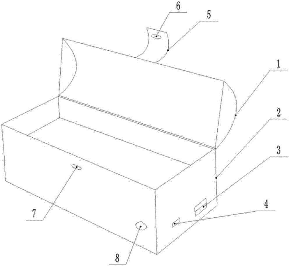
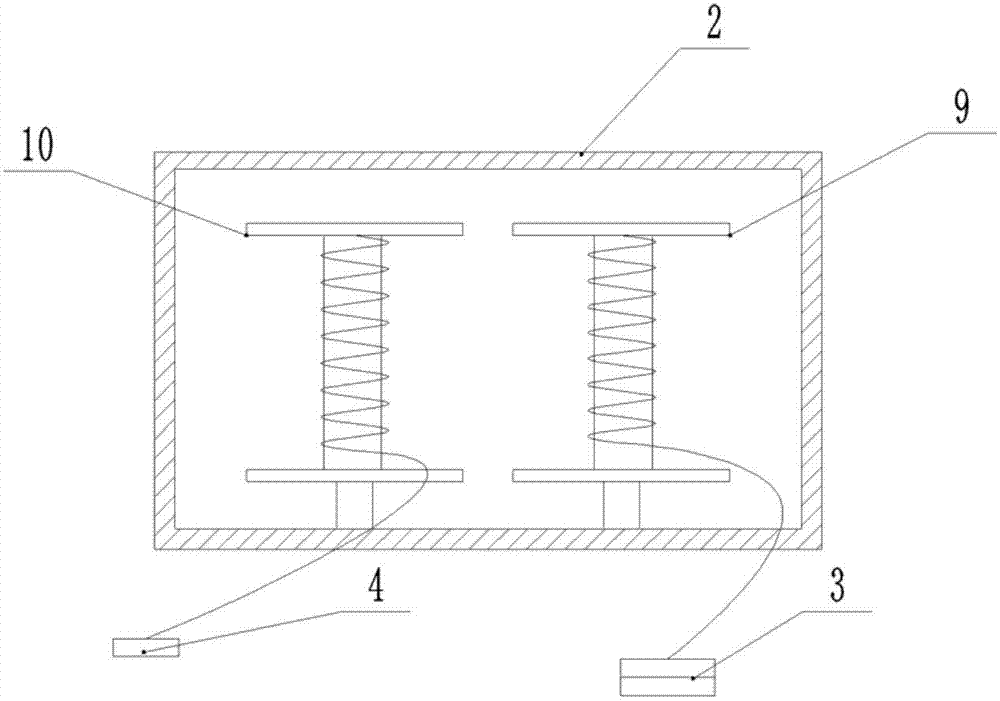
[0022] Such as figure 1 As shown, a kind of spectacle case with power supply comprises a rechargeable power supply, a hinged upper cover 1 and a lower cover 2, a power switch 8 is installed on the power supply, the power switch 8 is located at the right end of the lower cover 2, and the lower cover 2 The interior is a cavity structure; such as figure 2 As shown, the first winding roller 9 and the second winding roller 10 connected in rotation are installed in the cavity, and a spring is installed between the first winding roller 9 and the second winding roller 10 and the bottom of the cover respectively, charging The interface 4 and the charging end of the power supply are connected with a first wire, the first wire is wound on the first wire roller, the output interface 3 and the output end of the power supply are connected with a second wire, and the second wire is wound on the second winding roller 10 The power supply is fixedly placed in the cavity, and the right side of...

Embodiment 2

[0025] On the basis of Embodiment 1, a heat insulation layer is placed between the power supply and the heating wire, and the heat insulation layer is preferably glass wool; a sealing strip is pasted on the closed surface of the upper cover 1 and the lower cover 2, and the sealing strip is made of rubber; A torsion spring is installed at the hinge of the upper cover 1 and the lower cover 2 to facilitate automatic closing or opening, and a motor is installed inside the curved surface of the upper cover 1, such as image 3 As shown, a chute 11 is installed on the left and right sides of the spectacle case, and a slidable scraper 12 is installed in the chute 11. A spring is connected to one end of the scraper 12 and the chute 11, and a spring is connected between the scraper 12 and the output shaft of the motor. A string is connected, and the motor and the heating wire are connected in series in the circuit; when the glasses need to be cleaned and wiped, the power switch 8 is turn...


PUM


Abstract

The invention belongs to the technical field of glasses box equipment and particularly discloses a glasses box with a power supply. The glasses box includes a chargeable power supply, and an upper cover and a lower cover hinged to each other; a switch is arranged on the power supply. A cavity is formed in the lower cover. A first wire winding roller and a second wire winding roller are disposed inthe cavity in a rotation connection manner. Springs are arranged respectively between the first wire winding roller and the cover bottom and between the second wire winding roller and the cover bottom. The power supply is arranged in the cavity. An output interface and a charging interface for charging the power supply are arranged in the outer side of the lower cover. The glasses box can removemoisture on glasses and also can charge an electronic device, so that a problem of inconvenience to a user who wearing the glasses since moisture forms on the glasses lens in cold day and the user needs to wipe the glasses lens by taking out a glasses cloth from a glasses box in the prior art.

Description

technical field [0001] The invention belongs to the technical field of spectacle case equipment, and specifically discloses a spectacle case with a power supply. Background technique [0002] Glasses are widely used in various fields. In terms of functions, glasses are divided into myopia glasses, reading glasses, astigmatism glasses, windproof sand glasses, sunglasses, UV protection glasses, welding glasses, infrared protection glasses, etc. Your own glasses are both beautiful and can protect your eyes. [0003] Glasses are often placed in a glasses case. When traveling, the wearer usually needs to carry the glasses case with him and also the power bank, which increases the number of items that travelers carry with them. The possibility of loss is greatly increased, and the time for storing items is increased. [0004] In view of the above problems, Chinese patent CN205757810U discloses a spectacle case, which includes an upper case body and a lower case body formed with ...

Claims


Application Information

Patent Timeline
Patent Type & Authority Applications(China)
IPC IPC(8): A45C11/04A45C13/02H02J7/00
CPCA45C11/04A45C13/02H02J7/0042
Inventor 伊娃
Owner 伊娃
Learn More