Solid EPS module wall body and construction method thereof

A wall and solid technology, applied in the direction of walls, building components, buildings, etc., can solve the problems of slow construction, poor thermal insulation effect, heavy weight of assembled components, etc., and achieve low labor intensity, light weight and fast construction speed Effect

Active Publication Date: 2018-04-27
李文升
View PDF8 Cites 0 Cited by
  • Summary
  • Abstract
  • Description
  • Claims
  • Application Information

AI Technical Summary

Problems solved by technology

[0004] The invention provides a solid EPS module wall and its construction method to solve the problems of heavy weight of assembled components, slow construction and poor overall thermal insulation effect

Method used


Image

  • Solid EPS module wall body and construction method thereof
  • Solid EPS module wall body and construction method thereof
  • Solid EPS module wall body and construction method thereof

Examples


Embodiment 1

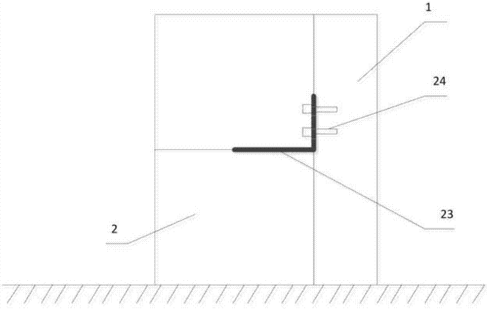
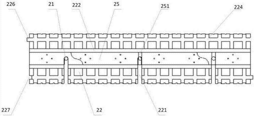
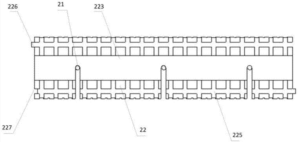
[0052] Such as Figure 1-5 As shown, the solid EPS module wall provided in the first embodiment includes a reinforced concrete pile 1 and an EPS wall surface 2, the reinforced concrete pile 1 is arranged on a load-bearing part of a building, and the EPS wall surface 2 includes a fixed vertical bar 21, EPS Module 22, right-angle fixture 23 and fixing nail 24, wherein the fixing vertical rib 21 is perpendicular to the ground, and the bottom is fixed in the concrete foundation; the EPS module 22 is a solid structure provided with a U-shaped groove 221 penetrating up and down, and the EPS module 22 is sleeved on the fixed vertical rib 21 through the U-shaped groove 221. The opening directions of the U-shaped grooves 221 of the two sets of EPS modules 22 assembled up and down are opposite. There is a positioning groove 222 in the middle of the top of the EPS module 2. There are positioning protrusions 223; as Figure 6 As shown, the right-angle fixture 23 is a sheet structure bent...

Embodiment 2

[0068] Another solid EPS module wall provided in Embodiment 2, in addition to the various components provided in Embodiment 1, also includes flat angle clamps 25, such as Figure 6 As shown, it also includes a boxer fixture 25, wherein the boxer fixture 25 is a straight boxer fixture, and is provided with a through second U-shaped slot 251, and the boxer fixture 25 is located below it to position the EPS module 22 Between the groove 222 and the positioning protrusion 223 of the upper EPS module 22 , the flat-angle clamp 25 is sleeved on the fixed vertical rib 21 through the second U-shaped clamping groove 251 . The opening direction of the first U-shaped groove 231 is opposite to that of the U-shaped groove 221 below it, and the opening direction of the second U-shaped groove 251 is opposite to the corresponding U-shaped groove 221 below it. The second U-shaped clamping groove 251 is matched with the fixed vertical rib 21 , and the flat-angle clamp 25 is matched with the posit...


PUM


Abstract

The invention discloses a solid EPS module wall body and a construction method thereof. The solid EPS module wall body comprises a reinforced concrete pile and an EPS wall surface. The EPS wall surface comprises a fixing vertical rib, EPS modules, a right angle clamping device and a fixing nail. The EPS modules sleeve the fixing vertical rib through U-shaped grooves, the opening directions of theU-shaped grooves of the two groups of the EPS modules assembled up and down are opposite, a positioning groove is formed in the middle of the top of each of the EPS modules, and a positioning bulge isarranged at the bottom; one right angle clamping arm of the right clamping device is located between the positioning groove of the EPS module under the right angle clamping arm and the positioning bulge of the EPS module above the right angle clamping arm and provided with a first U-shaped clamping groove, the other right angle clamping arm is located between the EPS module and the reinforced concrete pile and provided with a through fixing hole, and is fixed on the reinforced concrete pile through the fixing nail. The solid EPS module wall body has light weight, fast construction, good heatpreservation and thermal insulation performances, fireproof and dampproof functions and low construction cost.

Description

technical field [0001] The invention relates to the construction field, in particular to a solid EPS module wall and a construction method thereof. Background technique [0002] As people's demand for housing continues to increase, their demand for building materials is also increasing year by year. EPS polystyrene foam (Expanded Polystyrene, referred to as EPS) is a light polymer that uses polystyrene The resin is added with a foaming agent, and heated to soften at the same time, generating gas to form a foam with a rigid closed-cell structure. Therefore, as an ideal building material, it has been widely used in the construction field. Processing EPS into EPS modules for house construction is a rural self-built house model vigorously promoted by the Ministry of Construction. [0003] In the prior art, the exterior wall of the prefabricated building has poor thermal insulation performance, heavy weight, slow construction and short service life. In addition, due to the poor...

Claims


Application Information

Patent Timeline
IPC IPC(8): E04B2/64
CPCE04B2/64
Inventor 李文升
Owner 李文升
Why Eureka
Try Eureka