Ultrasonic probe correction method and system

A technology of correction system and correction method, which is applied in the field of ultrasonic detection, can solve problems such as inaccurate transmission and reception focus, poor image resolution and contrast, and achieve the effect of ensuring accuracy and improving detection effect

Active Publication Date: 2018-04-27
QISDA SUZHOU +1
View PDF6 Cites 10 Cited by
  • Summary
  • Abstract
  • Description
  • Claims
  • Application Information

AI Technical Summary

Problems solved by technology

[0004] The purpose of the present invention is to provide a calibration method and system for ultrasonic probes, which can solve the technical problems of i

Method used


Image

  • Ultrasonic probe correction method and system
  • Ultrasonic probe correction method and system
  • Ultrasonic probe correction method and system

Examples


no. 1 example

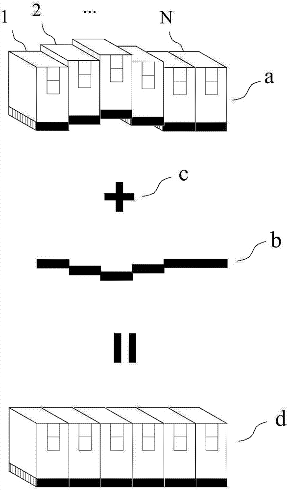
[0038] The invention provides a method for calibrating an ultrasonic probe, which determines the calibration information according to the measurement result, so as to provide the basis for calculating the transmitting and receiving beams of the ultrasonic system. Such as figure 1 As shown, due to the limited process capability of the ultrasonic probe, there are differences between the planes or line planes formed by the array elements of the probe. Taking a one-dimensional linear array probe with N array elements as an example, the arrangement of the array elements is not actually distributed in a straight line. At this time, it is necessary to determine the real distribution parameter a of the plane error through measurement, and perform calculations based on a to obtain correction information b, which can be provided to the ultrasonic system for compensation calculation c, after compensation and correction, the array elements present an ideal linear or planar arrangement d. ...

no. 2 example

[0059] Figure 3A and 3B It is a structural diagram of the correction system of the ultrasonic probe 311 according to the second embodiment of the present invention. The present invention provides a calibration system 30 for an ultrasonic probe 311 , which determines calibration information based on measurement results to provide a basis for calculation of transmitting and receiving beams of the ultrasonic system. The system includes: a measurement module 31 , a control processing module 32 and a compensation module 33 , the measurement module 31 is coupled to the ultrasonic probe 311 , and the control processing module 32 is coupled to the compensation module 33 . The ultrasonic probe 311 to be tested can be a linear array, a phased array or other types of probes, and can be a one-dimensional or more than one-dimensional array.

[0060] The measurement module 31 is used to measure the time-of-flight of the ultrasonic signals emitted by all the array elements in the ultrason...


PUM


Abstract

The invention provides an ultrasonic probe correction method and system. The method comprises steps: the flight time of ultrasonic signals transmitted by all array elements in the ultrasonic probe under a set distance or set time is measured, a reference array element is selected, and a flight time difference/ratio/product between each array element and the reference array element is calculated; and according to the flight time difference/ratio/product, compensation parameters of each array element are calculated, and according to the compensation parameters, transmitting or receiving of the ultrasonic signals of each array element is compensated. According to the method and the system, compensation and correction on process errors of the ultrasonic probe array can be realized, and a basisis provided for compensation and calculation on beam transmitting and receiving by the ultrasonic system.

Description

technical field [0001] The invention relates to the field of ultrasonic detection, in particular to a correction of an ultrasonic probe. Background technique [0002] An ultrasound system includes an array of transducer elements for transmitting a set of ultrasound beams into an imaged subject and receiving a set of reflected ultrasound signals. In the current technology, the calculation of the transmitting beam and the receiving beam is based on the assumption that the ultrasonic probe has ideal flatness or linearity; in fact, due to the limited process capability of the ultrasonic probe, there are differences between the planes or line planes where the elements of the probe are located , the ideal flatness or linearity of the probe array cannot be guaranteed. If the beamforming calculation is performed without considering the actual process error of the ultrasonic probe, the focus of transmission and reception will be deteriorated, and the resolution and contrast of the fi...

Claims


Application Information

Patent Timeline
IPC IPC(8): G01S7/52G01N29/30
CPCG01N29/30G01S7/52004
Inventor 蒋富升
Owner QISDA SUZHOU
Why Eureka
Try Eureka