Automatic high-shear emulsifying machine

A high-shear emulsification machine, automatic technology, applied in the field of emulsification machine, can solve the problems of waste of manpower and time, material loss, cumbersome operation, etc., to prevent damage to the container, save manpower and time, and ensure the effect of emulsification

Inactive Publication Date: 2018-05-01
武汉纤然生物科技有限公司
View PDF0 Cites 2 Cited by
  • Summary
  • Abstract
  • Description
  • Claims
  • Application Information

AI Technical Summary

Problems solved by technology

[0003] However, in the actual operation of the existing high-shear emulsifier, firstly, due to the difference in parameters such as the type of the emulsified solution to be sheared and the height of the liquid level, it is necessary for personnel to manually adjust and set the penetration depth of the rotor, the rotation frequency, The emulsification time and other parameters need to be observed by a special person. The operation is cumbersome and wastes manpower and time; secondly, due to the high-speed rotation of the rotor, the container containing the material is often displaced. If the fixing device is not used to fix it, the rotor will contact the inner wall of the container. , causing unnecessary friction and causing damage to the container; third, the above-mentioned displacement makes the rotor no longer in the center of the emulsified solution to be sheared, which will affect the shearing emulsification effect; finally, the liquid is prone to splashing or splashing during the shearing process. Foam, causing material loss after overflowing the container, not only seriously affects the product quality of the sheared sample, but also pollutes the operating table

Method used


Image

  • Automatic high-shear emulsifying machine
  • Automatic high-shear emulsifying machine
  • Automatic high-shear emulsifying machine

Examples


Embodiment 1

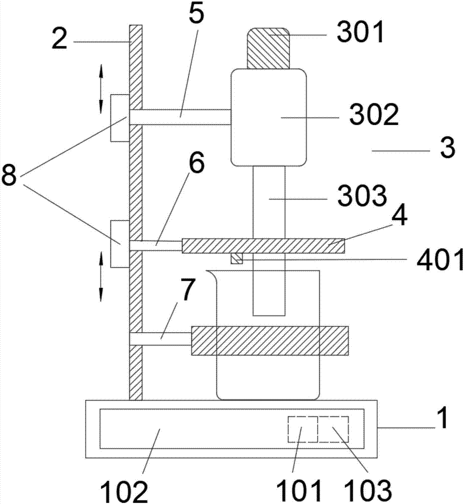
[0023] Such as Figure 1 to Figure 4 As shown, an automatic high-shear emulsification machine includes a console 1, a bracket 2, an emulsification device 3, and an annular cover plate 4; the console 1 includes a micro-control chip 101 electrically connected to each other, a touch screen 102, a timing module 103, the touch screen 102 is embedded on the side of the console 1, and the touch screen 102 sets and displays emulsification parameters; the bracket 2 is fixed on the console 1, and the emulsification device 3 automatically A motor 301, a fixed cylinder 302, and a rotor 303 are arranged from top to bottom, the motor 301 passes through the fixed cylinder 302 and is connected to the rotor 303, and a bearing is arranged between the fixed cylinder 302 and the rotor 303,

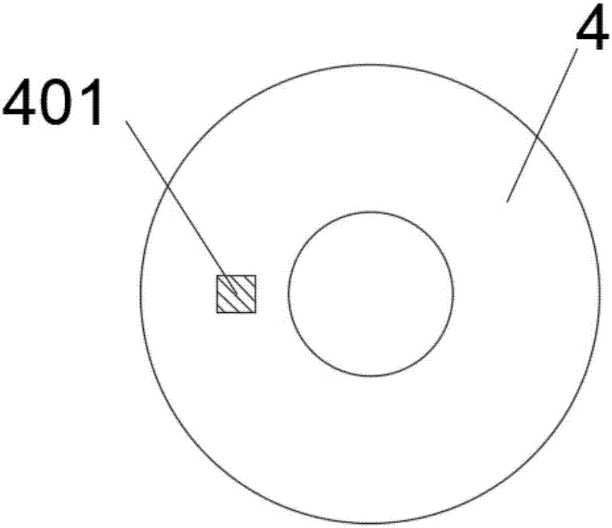
[0024] The rotor 303 passes through the middle of the annular cover plate 4, and the lower surface of the annular cover plate 4 is provided with a photoelectric sensor 401; the fixed cylinder 302 and the annu...


PUM


Abstract

The invention discloses an automatic high-shear emulsifying machine. The automatic high-shear emulsifying machine comprises a console, a bracket, an emulsifying device and an annular cover plate, wherein the console comprises a micro control chip and a touch screen embedded on a lateral surface of the console; the bracket is fixed on the console, the emulsifying device is provided with a motor, afixed cylinder and a rotor from the top down, wherein the motor penetrates through the fixed cylinder to be connected with the rotor, and the rotor penetrates through the middle part of the annular cover plate; a photoelectric sensor is arranged on the lower surface of the annular cover plate, the fixed cylinder and the annular cover plate are connected with the bracket through a first clamping device and a second clamping device respectively, a container is fastened on the console through a third clamping device under the second clamping device; transmission modules sliding up and down are further arranged at both the connecting parts of the first clamping device and the second clamping device with the bracket. The emulsifying machine realizes the automation of the emulsification processthrough the touch screen to effectively save manpower; the container is firmly fixed to avoid damage of the container; each emulsification parameter is precisely controlled to maximally improve the emulsification effect; and the annular cover plate can prevent liquid from splashing.

Description

technical field [0001] The invention belongs to the field of emulsifying machines, in particular to an automatic high-shear emulsifying machine. Background technique [0002] A high-shear emulsifier is a device that can efficiently, quickly, and evenly distribute one phase or multiple phases into another continuous phase, and usually the phases are immiscible with each other. The working principle of the high-shear emulsifier: Due to the high tangential velocity generated by the high-speed rotation of the rotor and the strong kinetic energy brought by the high-frequency mechanical effect, the material is subjected to strong mechanical and hydraulic shearing in the narrow gap between the stator and the rotor. The comprehensive effects of centrifugal extrusion, liquid layer friction, impact tearing and turbulence, so that the immiscible solid phase, liquid phase, and gas phase are gradually uniformly and finely dispersed and emulsified under the joint action of corresponding m...

Claims


Application Information

Patent Timeline
Patent Type & Authority Applications(China)
IPC IPC(8): B01F15/00B01F7/16B01F3/08
CPCB01F23/43B01F23/41B01F27/806B01F35/2112B01F35/22B01F35/221B01F35/42
Inventor 靖超
Owner 武汉纤然生物科技有限公司
Why Eureka
Try Eureka