Burr removing machining method based on torque control and burr removing system

A processing method and torque control technology, applied in the field of machining, can solve the problems of automatically adjusting the feed of deburring tools, reducing the machining accuracy and machining quality of parts, and affecting the machining accuracy of parts, so as to ensure the machining quality and consistency, The effect of good processing quality and high processing accuracy

Pending Publication Date: 2018-05-01
GUANGDONG HESHI AUTOMATION TECH CO LTD
View PDF6 Cites 3 Cited by
  • Summary
  • Abstract
  • Description
  • Claims
  • Application Information

AI Technical Summary

Problems solved by technology

Although the propulsion method of the propulsion mechanism can also complete the deburring treatment on the surface of the part, this kind of propulsion method is not intelligent enough, so that when the blank size of the workpiece has a large tolerance range, the propulsion mechanism cannot automatically adjust the size of the part The feed rate during the movement of the deburring tool not only affects the processing accuracy of the part, but also easily causes a strong collision between the deburring tool and the part at the beginning of contact, which makes the deburring tool or the part easy to be damaged
In addition, the existing deburring equipment is still unable to accurately compensate the wear of the deburring tool. The wear compensation of the deburring tool can only be adjusted through the work experience of the equipment designer, which reduces the machining accuracy and processing quality of the parts. quality

Method used


Image

  • Burr removing machining method based on torque control and burr removing system
  • Burr removing machining method based on torque control and burr removing system
  • Burr removing machining method based on torque control and burr removing system

Examples


no. 1 example

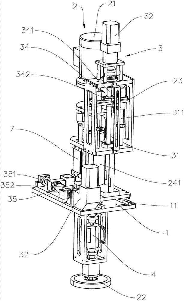
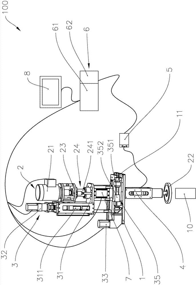
[0032] refer to figure 1 and figure 2 , the deburring system 100 includes a fixed seat 1 , a deburring mechanism 2 , a propulsion mechanism 3 , a torque sensor 4 , a torque amplifier 5 , a controller 6 , a counterweight cylinder 7 and a client 8 .

[0033] Wherein, the fixing base 1 is used to provide installation positions for the deburring mechanism 2 and the advancing mechanism 3, and the fixing base 1 can also be used to connect with the frame of the deburring equipment, so that the deburring system 100 can be installed on the deburring equipment on the rack.

[0034] The propulsion mechanism 3 is installed on the fixed seat 1, the deburring mechanism 2 is installed on the propulsion mechanism 3, and the propulsion mechanism 3 is used to drive the deburring mechanism 2 to move, so that the deburring tool 22 of the deburring mechanism 2 moves to the workpiece, and then realizes The workpiece 10 is deburred. Specifically, the propulsion mechanism 3 includes a mounting ba...

no. 2 example

[0066] Applying the inventive concept of the first embodiment of the deburring system, the difference between the second embodiment of the deburring system and the first embodiment is that the propulsion mechanism 3 of the second embodiment only includes a mounting base 31, a motor 32 and a ball screw assembly 34, the mounting base 31 is installed on the fixing base 1, the deburring mechanism 2 is slidably connected with the mounting base 31 along the axial direction of the driving end of the motor 21, the base body of the motor 32 is fixedly installed on the mounting base 31, the driving of the motor 32 The end is connected with the deburring mechanism 2, and the axis of the driving end of the motor 32 is parallel to the axis of the driving end of the motor 21. The ball screw assembly 34 includes a lead screw 341 and a lead screw nut 342 , the lead screw 341 is fixedly connected with the driving end of the motor 32 , the lead screw nut 342 is threaded with the lead screw 341 ,...

no. 3 example

[0069] Applying the inventive concept of the first embodiment of the deburring system, the third embodiment of the deburring system is different from the first embodiment in that the propulsion mechanism 3 of the third embodiment only includes a mounting base 31 and a motor 33, and the fixing base 1 A slide rail 11 is provided, and the mounting seat 31 is slidably connected with the slide rail 11 along the extending direction of the slide rail 11. The deburring mechanism 2 is installed on the mounting seat 31, and the seat body of the motor 33 is installed on the fixed seat 1. The motor 33 The driving end is connected with the mounting base 31.

[0070] The difference between the deburring processing method of this embodiment and the above-mentioned embodiment of the deburring processing method based on torque control is that the deburring processing method of this embodiment does not include the deburring mechanism 3 driving the deburring tool 22 of the burring mechanism 2. T...


PUM


Abstract

The invention provides a burr removing machining method based on torque control and a burr removing system. The burr removing system comprises a pushing mechanism, a burr removing mechanism with a motor, a torque sensor, a torque amplifier and a controller with a body and an analog-digital converter. The burr removing machining method comprises the steps that a run program is written into the body, and a standard threshold value is set in advance; a burr removing tool is driven by the pushing mechanism according to the run program to move to a workpiece; the current load torque of the motor isdetected through the torque sensor, the current load torque is converted into standard analog signals through the torque amplifier, and the standard analog signals are converted into digital currentsignals through the analog-digital converter; and the digital current signals are obtained by the body, the standard threshold value is compared with the digital current signals, and the feeding amount of the pushing mechanism is adjusted according to the comparative result. By means of the burr removing device and the burr removing machining method, the burr removing tool feeding amount can be adjusted according to friction force borne by the burr removing tool, and the beneficial effects of being high in machining accuracy and good in machining quality are achieved.

Description

technical field [0001] The invention relates to the technical field of mechanical processing, in particular to a torque control-based deburring processing method and a deburring system applying the method. Background technique [0002] During the milling, turning, drilling and other mechanical processing of products, the processed parts are often prone to burrs and flashes, which not only affect the surface quality of the parts, but also affect the performance of the parts. The traditional processing method is to deburr the parts manually, but the manual processing method has disadvantages such as low production efficiency and high labor intensity. Therefore, many companies are gradually beginning to use mechanical equipment to replace the traditional manual processing of parts. Perform deburring treatment to improve production efficiency and deburring accuracy of parts, and ensure the quality of parts. [0003] The deburring equipment currently on the market generally uses...

Claims


Application Information

Patent Timeline
Patent Type & Authority Applications(China)
IPC IPC(8): B24B9/00B24B47/20B24B51/00
CPCB24B9/00B24B47/20B24B51/00
Inventor 王丽萍李卫彤张云彦朱惠德
Owner GUANGDONG HESHI AUTOMATION TECH CO LTD
Why Eureka
Try Eureka