

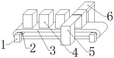
Sponge mat feeding device of limit box assembling equipment
A technology for assembling equipment and sponge pads, which is applied in the field of mechanical equipment, can solve problems such as low work efficiency, easy tilting of sponge pads, and low mechanization of sponge pad feeding, and achieve the effect of improving efficiency and continuity
- Summary
- Abstract
- Description
- Claims
- Application Information
AI Technical Summary
Problems solved by technology
Method used
Image

Examples
specific Embodiment approach
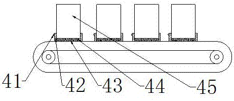
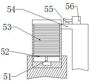
[0024] Specific embodiments: when the staff uses the present invention, the sponge pad body 53 is stacked on the upper end surface of the carrier plate 52 inside the containing box 45, and then the staff places the containing box 45 on the electromagnet 43 between the fixed baffles 42, The staff presses the switch button 41 to connect the power supply between the storage battery and the electromagnet 43, and the electromagnet 43 works closely with the magnet block 44 through the magnetic attraction force, thereby completing the fixing of the containing box 45, and then the staff makes it connect with the rotating shaft The connected motor runs, the motor drives the roller 2 to rotate, the roller 2 rotates to drive the conveyor belt 3 to move, the conveyor belt 3 moves to drive the electromagnet 43 to move, the electromagnet 43 moves to drive the container 45 to move, and the container 45 moves to drive the sponge pad body 53 to move , so that the container 45 is moved to the po...
PUM
 Abstract
Description
Claims
Application Information