Straw smashing and rod making device for anaerobic fermentation biogas production

A straw crushing and anaerobic fermentation technology, applied in biochemical equipment and methods, gas production bioreactors, biochemical instruments, etc., can solve the problems of increasing transportation costs and storage space, reducing gas production rate, and strengthening transportation costs, etc. Achieve the effects of reducing long-distance transportation costs, reducing transportation volume, and increasing inventory capacity

Pending Publication Date: 2018-05-01
安阳利浦筒仓工程有限公司
View PDF0 Cites 1 Cited by
  • Summary
  • Abstract
  • Description
  • Claims
  • Application Information

AI Technical Summary

Problems solved by technology

Because the specific gravity of organic matter scum is smaller than that of water, they all float on the upper part of the reaction liquid after entering the tank, while the bacteria in the anaerobic tank are in the middle and lower part of the tank, and gradually form a hard shell on the liquid surface as the straw on the liquid surface increases. , at the same time, there is incomplete anaerobic fermentation, stratification of the material in the generator, the material in the tank cannot be effectively decomposed and reacted, and the gas production rate is reduced. Can not solve the problem of floating and encrustation, severe state can stop the anaerobic reaction
[0004] In addition, the straw is transported to the biogas production area after the crops are harvested. Due to the large size of the straw, if the transportation distance is greater than 1.5 kilometers, the transportation cost will be greatly increased. The collection radius of medium and large biogas production is generally within 3-5 kilometers. Therefore, The bulk of straw will greatly increase the transportation cost and storage space

Method used


Image

  • Straw smashing and rod making device for anaerobic fermentation biogas production
  • Straw smashing and rod making device for anaerobic fermentation biogas production

Examples


Embodiment Construction

[0020] The present invention will be further described in conjunction with embodiment (accompanying drawing):

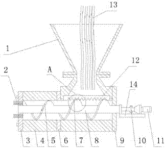
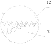
[0021] like figure 1 , figure 2 As shown, the straw crushing and rod making equipment of the present invention includes an auger mandrel 8 provided with a screw auger installed in the cavity 4 coaxially with the cavity of the equipment, and the auger is formed as an extrusion The front and back of the crushing section and the crushing section are composed of two sections of spiral augers; the outer contour of the spiral auger as the crushing section at the position of the feeding port of the cavity 4 is provided with an auger end cutting knife 7 with a toothed edge. , the toothed edge on the auger end cutting knife 7 and the toothed edge of the upper cutter 12 installed at the position of the feed port of the cavity 4 are in a shearing engagement relationship; as the extruding section 5 The outer contour of the spiral auger section is a smooth surface and has a dy...


PUM


Abstract

The invention relates to a straw smashing and rod making device for anaerobic fermentation biogas production. The straw smashing and rod making device for anaerobic fermentation biogas production is characterized by comprising an auger spindle (8), wherein the auger spindle (8) is coaxially arranged in a cavity body (4) of the device and is provided with a spiral auger; the spiral auger is formedby two sections of spiral augers used as an extruding section and a smashing section and continuously arranged front and back; an auger end cutting knife (7) with a toothed cutting edge is arranged onan outer contour of the spiral auger used as the smashing section located at a feed inlet position of the cavity (4); the toothed cutting edge on the auger end cutting knife (7) is matched with a toothed cutting edge of an upper cutting knife (12) arranged at the feed inlet position of the cavity (4) in a shearing-meshing way; an outer contour of the spiral auger section used as the extruding section (5) is a smooth surface, and is in movable fit to the cavity body (4) and an inner cavity of a baffle ring (6); a rod making hole plate mold (3) is arranged on the front end of the cavity body ofthe equipment; a plurality of straw rod forming holes are formed in the rod making hole plate mold (3).

Description

technical field [0001] The invention relates to an equipment for crushing crop waste straws, tree weeds, strips, plant woody branches, stems, necks, roots and other materials and extruding them into cylindrical rods. The straw rods made by the equipment are particularly It is suitable for anaerobic fermentation biogas production of large-scale crop waste straws. Background technique [0002] China is a large agricultural country in the world, and there are hundreds of millions of tons of crop waste straw every year. The comprehensive utilization of straw is a systematic project that the country will carry out for a long time, and the biogas production of straw is the first choice. The straw is digested and decomposed by microorganisms in the anaerobic tank to produce biogas, which can be used as domestic gas in rural areas, can also be made into CNG, and can also be used for power generation. Biogas residue and biogas slurry are high-quality green organic crop fertilizers. ...

Claims


Application Information

Patent Timeline
IPC IPC(8): C12M1/107
CPCC12M21/04C12M45/02
Inventor 王国防张海刘海明张一维曲跃刚刘瑞超赵阳
Owner 安阳利浦筒仓工程有限公司
Why Eureka
Try Eureka