Automatic sediment division and ejection structure with headwork annular irregular section

A technology with special-shaped cross-sections and structures, which is applied in river regulation and other directions, and can solve the problems of large floor area of ​​grit chambers, strict water flow requirements, and slow filtration.

Inactive Publication Date: 2018-05-01
ZHEJIANG UNIV OF WATER RESOURCES & ELECTRIC POWER
View PDF8 Cites 1 Cited by
  • Summary
  • Abstract
  • Description
  • Claims
  • Application Information

AI Technical Summary

Problems solved by technology

[0002] In most water diversion irrigation areas in northern China, sediment transport and its control have always been a difficult problem for those who design irrigation systems. Sediment is often seriously deposited in water diversion channels at all levels in these irrigation areas; According to the current situation, 30.8% of the sediment in Henan Province is deposited in the water diversion canal system, and 38.5% in Shandong Province; It affects the water delivery efficiency and normal operation of the irrigation district. Therefore, many irrigation districts spend a lot of manpower, material resources and financial resources on dredging the channel every year; The wind causes sand to fly all over the sky, which seriously damages the local ecological environment; the grit chamber is currently the main way to deal with sediment in most irrigation areas in China, but the grit chamber occupies a large area and has a short service life. At present, the upstream areas of most irrigation areas have basically There is no expandable sand sinking depression, and it is urgent to find new ways to control sediment in irrigation areas; sand discharge vortex tubes, sand discharge funnels and other sand discharge facilities have shown good sand discharge and water saving effects in application, but their applicable conditions are

Method used


Image

  • Automatic sediment division and ejection structure with headwork annular irregular section
  • Automatic sediment division and ejection structure with headwork annular irregular section
  • Automatic sediment division and ejection structure with headwork annular irregular section

Examples


Embodiment Construction

[0016] The present invention will be further described below in conjunction with the drawings.

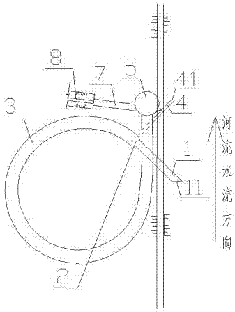
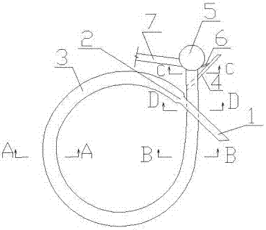
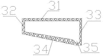
[0017] Such as Figure 1-7 As shown, the annular shaped cross-section automatic sand discharging structure of the canal head of the present invention is composed of a rectangular section section 1, a water inlet 11, a connecting section 2, a special section section 3, a top plate 31, an outer plate 32, an inner plate 33, and a bottom plate. 34. Sand collecting trough 35, trapezoidal section 36, first section of sand discarding 4, discarding sand port 41, large-diameter vertical tube 5, tube top cover 51, tube bottom plate 52, second section of discarding sand 6, output section 7, diversion channel 8 , The connecting hole 9 is composed of the output section 7 and the diversion canal 8 with the same water passing area, and the water passing area is determined by the irrigation demand design. The water inlet 11 has a 30% larger water passing area than the output section 7; 3 The water p...


PUM


Abstract

The invention provides an automatic sediment division and ejection structure with a headwork annular irregular section. The automatic sediment division and ejection structure is composed of a rectangular section, a water inlet, a connecting section, an irregular section, a top plate, an outside plate, an inside plate, a base plate, a sediment collection slot, a trapezoidal section, a sediment discard section I, a sediment discard port, a major diameter vertical barrel, a barrel top cap, a barrel bottom plate, a sediment discard section II, an output section, a diversion canal and a communication pore. The automatic sediment division and ejection structure with the headwork annular irregular section is used for sediment division, large space is not required for sedimentation, and the clearing and transport of sediment are not required; water flow with high sediment concentration can be automatically returned to an original river channel in the sediment division process, and the site, manpower and cost are saved; the sediment ejection effect is good; and the structure can also be buried underground under the proper conditions, so that a ground position is not occupied.

Description

Technical field [0001] The invention belongs to the technical field of water conservancy engineering, and specifically is a canal head ring-shaped special-shaped cross-section automatic sand separation structure. Background technique [0002] In most water diversion irrigation areas in northern China, sediment transport and its control have always been a difficult problem for people who design irrigation systems. The water diversion channels of these irrigation areas often have serious sedimentation; according to the statistics of the Yellow River irrigation areas from 1958 to 1990 In fact, 30.8% of the sediment in Henan Province is deposited in the diversion canal system, compared with 38.5% in Shandong Province. Under the current diversion engineering technology, it is difficult to transport all the sediment over long distances, and a large amount of sediment is deposited in the channel, which is serious. It affects the water delivery efficiency and normal operation of the irri...

Claims


Application Information

Patent Timeline
IPC IPC(8): E02B3/02
Inventor 秦鹏程春梅徐蔚王海波吴昉李海涛秦植海
Owner ZHEJIANG UNIV OF WATER RESOURCES & ELECTRIC POWER
Why Eureka
Try Eureka