Rotor position measurement method of transverse flux switch reluctance motor without position sensor

A technology of switched reluctance motor and sensor rotor, which is applied in electronic commutation motor control, electrical components, control system and other directions, can solve the problems such as the large amount of calculation of the flux linkage method and the difficulty in realizing the algorithm of the inductance partition method. Achieving, high-precision effects

Active Publication Date: 2018-05-01
南通大学技术转移中心有限公司
View PDF5 Cites 4 Cited by
  • Summary
  • Abstract
  • Description
  • Claims
  • Application Information

AI Technical Summary

Problems solved by technology

[0004] The purpose of the present invention is to provide a method for measuring the rotor position of a transverse flux switched reluctance motor without a position sensor, which solves the problems of misleading conduction in the traditional inductance partition method and the large calculation amount of the flux linkage method, which is difficult to implement

Method used


Image

  • Rotor position measurement method of transverse flux switch reluctance motor without position sensor
  • Rotor position measurement method of transverse flux switch reluctance motor without position sensor
  • Rotor position measurement method of transverse flux switch reluctance motor without position sensor

Examples


Embodiment Construction

[0027] The present invention will be described in detail below in combination with specific embodiments.

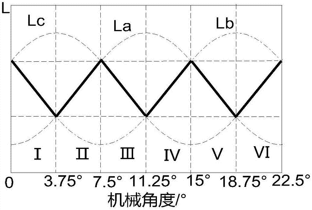
[0028] Taking the three-phase 16 / 16-pole TFSRM as a prototype, the phase winding voltage equation of the transverse flux switched reluctance motor is as follows:

[0029]

[0030] where U k is the kth phase winding voltage, i k is the kth phase winding current, R k is the kth phase resistance, L k is the kth phase winding inductance, Ω is the rotor angular velocity, θ is the rotor position angle;

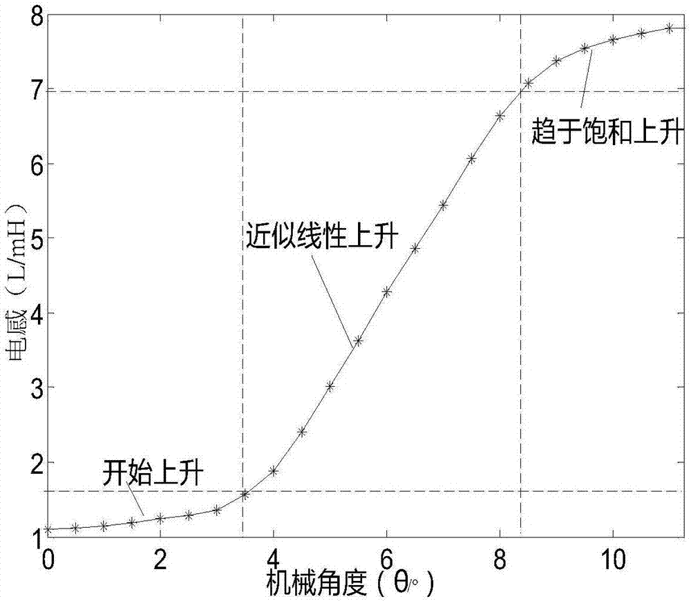
[0031] The high-frequency pulse voltage injected during position detection has a small amplitude and short action time. The current generated by the magnetic circuit is not saturated, and the current changes approximately linearly, and Ω=0 in the static state, ignoring the electromagnetic saturation effect and resistance voltage drop. , the phase winding equation (1) can be simplified as:

[0032]

[0033] After discretizing formula (2), we can get:

[0034]

[0...


PUM


Abstract

The invention discloses a rotor position measurement method of a transverse flux switch reluctance motor without a position sensor. The rotor position measurement method comprises the steps of settingan initial position angle of the motor, and applying a high-frequency pulse voltage to an A phase; adding a step to the initial position angle of the motor, and sequentially calculating an inductancevalue corresponding to each angle to obtain an A phase angle-inductance relation curve; dividing the inductance curve in a mechanical angle period into six regions, performing fitting by employing aquadratic polynomial method to obtain an ideal inductance curve, analyzing the ideal inductance curve, selecting appropriate low-threshold inductance TL, and obtaining a starting phase logic in the mechanical angle period according to a relation between three-phase inductance and the TL in each region; simultaneously calculating a three-phase inductance value from a three-phase injection high-frequency pulse voltage, comparing the three-phase inductance value with the starting phase logic, and determining a starting phase; and injecting a next conduction phase of the starting phase into the high-frequency pulse voltage, switching off the starting phase after a commutation threshold is reached, and conducting the next phase to achieve commutation running. The rotor position measurement method is easy to implement and is relatively high in accuracy.

Description

technical field [0001] The invention belongs to the technical field of position sensorless rotor position detection of switched reluctance motors, and relates to the precise measurement of the position sensorless rotor of switched reluctance motors. Background technique [0002] Transverse Flux Switch Reluctance Motor (TFSRM for short) has the characteristics of high torque density, good low-speed performance, strong fault tolerance, and large starting torque. It has broad applications in electric vehicles, wind power generation and industrial fields. application prospects, but there are still many areas to be explored. The position detector of the TFSRM motor detects the rotor position in real time, sends the collected rotor position signal to the controller, and the controller processes and calculates the signal, and generates a corresponding control signal to drive the conduction of the main switch tube in the power converter And off, in order to realize the real-time po...

Claims


Application Information

Patent Timeline
Patent Type & Authority Applications(China)
IPC IPC(8): H02P6/185
CPCH02P6/185
Inventor 瞿遂春徐杨邱爱兵姜亚海钟永彦陈飞王胜锋谢晨曦曹礼勇
Owner 南通大学技术转移中心有限公司
Why Eureka
Try Eureka