

CT system and detection device thereof
A technology of detection device and accommodating cavity, which is applied in medical science, instruments for radiological diagnosis, diagnosis, etc., to achieve the effect of ensuring image imaging effect, facilitating diagnosis, and ensuring the stability of correction
- Summary
- Abstract
- Description
- Claims
- Application Information
AI Technical Summary
Problems solved by technology
Method used
Image

Examples
Embodiment Construction
[0042] In order to make the purpose, technical solution and advantages of the present invention clearer, the CT system and its detection device of the present invention will be further described in detail below through embodiments and in conjunction with the accompanying drawings. It should be understood that the specific embodiments described here are only used to explain the present invention, not to limit the present invention.
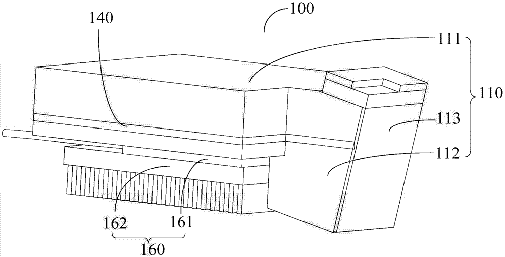
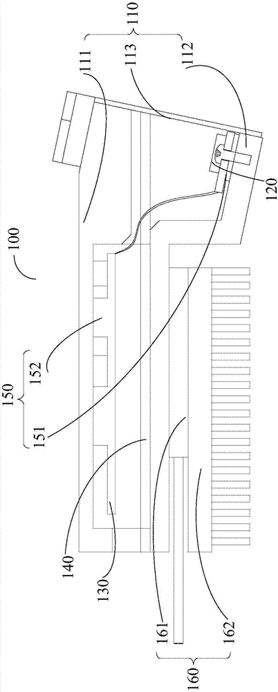
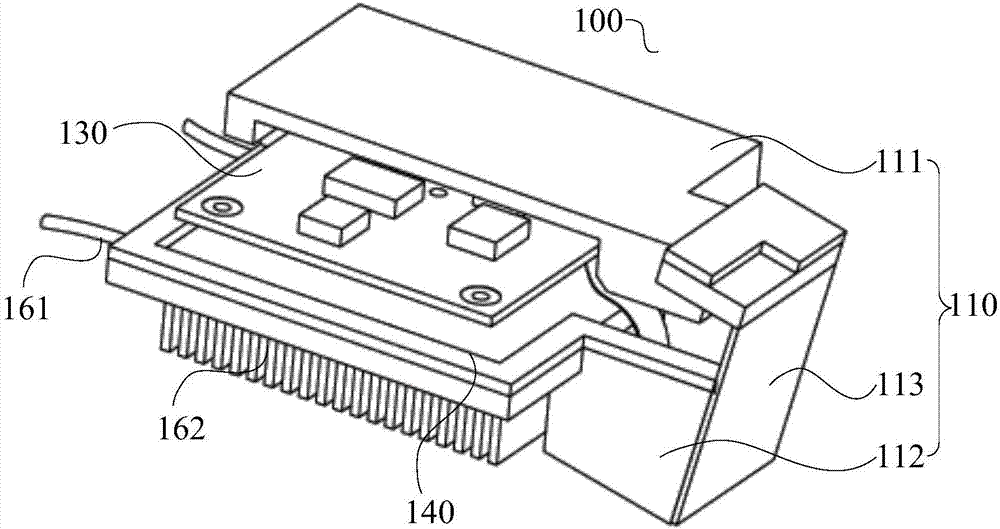
[0043] see Figure 1 to Figure 3 The present invention provides a detection device 100, which is arranged in a scanning system. In the present invention, the scanning system refers to a CT system, and the detection device 100 is used to detect radiation from a radiation source. In the present invention, the ray source refers to the tube, which emits X-rays. The detection device 100 of the present invention is used to detect the X-rays emitted by the tube of the CT system, so as to detect the ray intensity of the tube and track the focal position of...
PUM
 Abstract
Description
Claims
Application Information