Automotive headlight lighting system and automotive based on amplitude and phase modulation

A technology for automotive headlights and lighting systems, applied in the field of optical lighting systems, can solve problems such as low design freedom, waste of resources, and inability to realize headlights, and achieve the effects of easy design and processing and reduced complexity

Active Publication Date: 2019-09-13
HUIZHOU FRONT OPTOELECTRONIC TECH CO LTD
View PDF3 Cites 0 Cited by
  • Summary
  • Abstract
  • Description
  • Claims
  • Application Information

AI Technical Summary

Problems solved by technology

Traditional car headlights, one headlight can only project a fixed-shaped lighting light field. It is necessary to separate high beam and low beam to realize high beam and low beam respectively. High beam and low beam require two systems. cause waste of resources
[0003] Moreover, traditional automotive headlights need to design two different free-form lenses or reflectors. Although the current technical design of free-form lenses and reflectors is relatively mature, their design costs are high, the design freedom is low, and it is not easy to install. The problem of slow mass production is still obvious
[0004] Traditional car headlights cannot realize the projection of some fancy patterns, and cannot meet the needs of some consumers who have psychological expectations in this regard

Method used


Image

  • Automotive headlight lighting system and automotive based on amplitude and phase modulation
  • Automotive headlight lighting system and automotive based on amplitude and phase modulation
  • Automotive headlight lighting system and automotive based on amplitude and phase modulation

Examples


Embodiment Construction

[0029] Embodiments of the present invention will be described in detail below. It should be emphasized that the following description is only exemplary and not intended to limit the scope of the invention and its application.

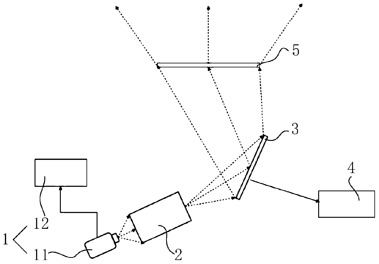
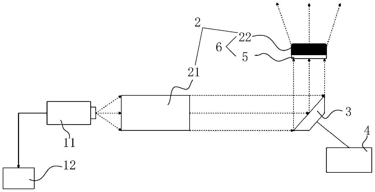
[0030] refer to figure 1 , the automotive lighting system based on amplitude and phase modulation includes an illumination source generator 1, a beam shaping system 2, a spatial light modulator 3, a spatial light modulation control system 4 and a diffractive optical element 5; the illumination source generator 1 is used to emit an illumination beam , the beam shaping system 2 is used to shape the illumination beam into a divergent beam, the spatial light modulator 3 is used to modulate the amplitude of the illumination beam, the diffractive optical element 5 is used to modulate the phase of the illumination beam, and the spatial light modulation control The system 4 is used to control the spatial light modulator 3; the illumination beam emitted by the ...


PUM


Abstract

The invention provides an automobile illumination system based on amplitude and phase modulation and an automobile. The automobile illumination system comprises an illumination light source generator,a light beam shaping system, a spatial light modulator, a spatial light modulation control system and a diffractive optical element. The illumination light source generator is used for generating illumination light beams. The light beam shaping system is used for shaping the illumination light beams into divergence light beams. The spatial modulator is used for modulating the amplitude of the illumination light beams. The diffractive optical element is used for modulating the phase of the illumination light beams. The spatial light modulation control system is used for controlling the spatiallight modulator. The illumination light beams generated by the illumination light source generator sequentially pass the spatial light modulator and the diffractive optical element. The light beam shaping system is arranged between a light path between the illumination light source generator and the diffractive optical element. The automobile comprises the automobile illumination system. By the adoption of the automobile illumination system and the automobile, projection of different light patterns can be achieved.

Description

technical field [0001] The present invention relates to an optical lighting system, in particular to an automotive lighting system based on amplitude and phase modulation and a car including the lighting system. Background technique [0002] Automobile headlight lighting is an important guarantee for driving safety at night. In the technology of automobile headlight lighting, smart car lights have become a development trend. Traditional car headlights, one headlight can only project a fixed-shaped lighting light field. It is necessary to separate high beam and low beam to realize high beam and low beam respectively. High beam and low beam require two systems. cause waste of resources. [0003] Moreover, traditional automotive headlights need to design two different free-form lenses or reflectors. Although the current technical design of free-form lenses and reflectors is relatively mature, their design costs are high, the design freedom is low, and it is not easy to install...

Claims


Application Information

Patent Timeline
Patent Type & Authority Patents(China)
IPC IPC(8): F21S41/141F21S41/20F21S41/25F21S41/675F21W102/13F21W107/10F21Y115/10
Inventor 苏萍宋昱铭马建设谭峭峰
Owner HUIZHOU FRONT OPTOELECTRONIC TECH CO LTD
Why Eureka
Try Eureka