
Grating projection and recognition method

An identification method and grating technology, applied in the direction of using optical devices, measuring devices, instruments, etc., can solve the problems of difficulty in identifying and distinguishing light strips, and achieve the effects of avoiding approximate errors, easy identification, and improving measurement accuracy.

Inactive Publication Date: 2009-05-27
BEIHANG UNIV
View PDF4 Cites 0 Cited by
  • Summary
  • Abstract
  • Description
  • Claims
  • Application Information

AI Technical Summary

Problems solved by technology

[0002] In the 3D shape measurement system, the pattern projector mostly adopts a specially designed hardware system, and often can only project a pattern of a certain mode
However, when the density of the light stripes is too high, it is difficult to identify the light stripes, and it is often difficult to distinguish them.

Method used


Image

  • Grating projection and recognition method
  • Grating projection and recognition method
  • Grating projection and recognition method

Examples


Embodiment

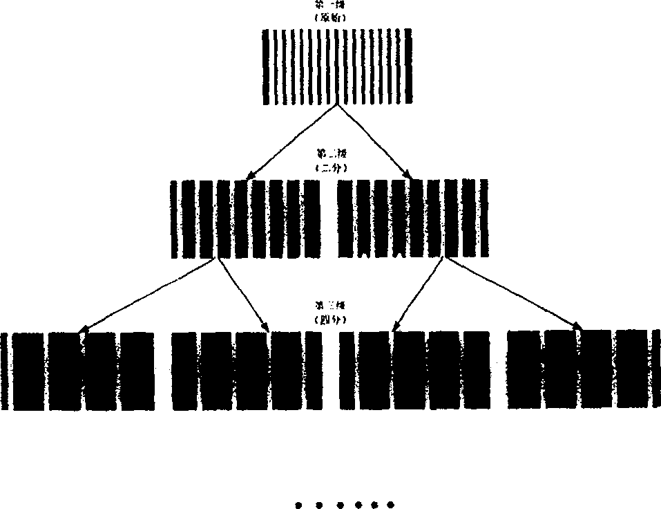
[0045] Such as image 3 The raw grating shown is measured on a display using 128 light bars. Apparently, because the light stripes are too dense, they are almost connected together, which brings great difficulty to the recognition of the light stripes. Therefore, we use the pyramid sub-grating projection method to project two sub-gratings, such as Figure 4 , Figure 5 shown. Then the sub-raster 1 and the sub-raster 2 are respectively coded by the spatial binary coding method. Figure 6-11 Shown is the pattern of spatial binary encoding for sub-grating 1, and the light bar intervals are 32, 16, 8, 4, 2, and 1, respectively.

[0046]Using the method of Stig (Kasden. Steg, an unbiased detector with a curved structure, Proceedings of the International Institute of Electrical and Electronics Engineers. Pattern Analysis and Machine Intelligence, 1998, 20(2): 113-125) Extract the light bar center of sub-grating 1, and according to the six coded images, use the method proposed b...


PUM


Abstract

The related improvement on high-density grating projection and recognition method comprises: applying 'pyramid sub-grating projection method' to refine the original grating, then recognizing the optical strip of the treated grating. This invention can implement grating projection of arbitrary density and mode, and can avoid error led by interpolation.

Description

technical field [0001] The invention belongs to the three-dimensional shape measurement technology of structured light, and relates to the improvement of a high-density grating projection and recognition method. Background technique [0002] In the 3D shape measurement system, the pattern projector mostly adopts a specially designed hardware system, and often can only project a pattern of a certain mode. In existing systems, some project a single light strip to achieve 3D shape measurement by scanning [Zhu Zhou et al., 3D Whole Body Scanner Based on Structured Light, Journal of Huazhong University of Science and Technology, 2004, Vol: 32(10): 7- 9], and some project a grating pattern formed by multiple light strips [Feng Zhanjun et al., 3D Active Vision Inspection Based on Grating, Metrology Technology, 2003, 5: 15-18]. In actual measurement, the greater the density of the grating light strips, the more detailed the three-dimensional shape data of the object can be obtained...

Claims


Application Information

Patent Timeline
Patent Type & Authority Patents(China)
IPC IPC(8): G01B11/24
Inventor 张广军魏振忠孙军华
Owner BEIHANG UNIV
Learn More