
Calibration device and calibration method for alignment of guidance radar mechanical axis and electrical axis

A calibration method and technology of mechanical axis, which are applied to measurement devices, optical devices, radio wave measurement systems, etc., can solve the problem of affecting the alignment accuracy of the mechanical axis and the electric axis, affecting the missile's ability to intercept and track the target, and the zero of the electric axis. The position and the zero position of the missile mechanical axis may not be precisely aligned, etc.

Active Publication Date: 2020-09-22
CHINA AIR TO AIR MISSILE INST
View PDF10 Cites 0 Cited by
  • Summary
  • Abstract
  • Description
  • Claims
  • Application Information

AI Technical Summary

Problems solved by technology

Alignment calibration at home and abroad is usually to calibrate the mechanical zero position and electrical zero position separately. If there is an installation error or structural deformation in the product assembly, it is difficult to eliminate the error by mechanical zero position calibration and electrical zero position calibration, which will affect Alignment accuracy of mechanical and electrical axes in the system
After the existing guidance radar is installed on the missile, only the zero position of the electrical axis of the guidance radar and the zero position of the mechanical axis of the missile are calibrated separately. Due to the inevitable system errors such as structural deformation and dimensional deviation during the production and assembly of the missile, the calibrated electrical axis The zero position of the axis and the zero position of the mechanical axis of the missile may not be precisely aligned. For a device such as a guided radar that detects targets tens of kilometers away, there will be a large deviation between the captured target position and the actual target position
In addition, when the guidance radar captures a distant target, there will be a circular deviation in the detection. This deviation should be smaller than the threshold value. The alignment accuracy of the threshold value and the electrical axis and mechanical axis will directly affect the interception and tracking of the target by the missile. ability

Method used


Image

  • Calibration device and calibration method for alignment of guidance radar mechanical axis and electrical axis
  • Calibration device and calibration method for alignment of guidance radar mechanical axis and electrical axis
  • Calibration device and calibration method for alignment of guidance radar mechanical axis and electrical axis

Examples


Embodiment Construction

[0023] The present invention can be explained in detail through the following examples, and the purpose of disclosing the present invention is to protect all technical improvements within the scope of the present invention.

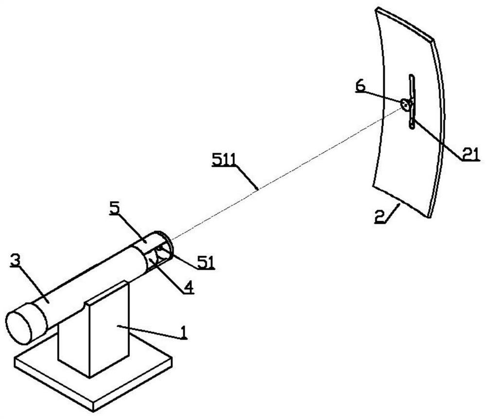
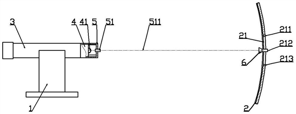
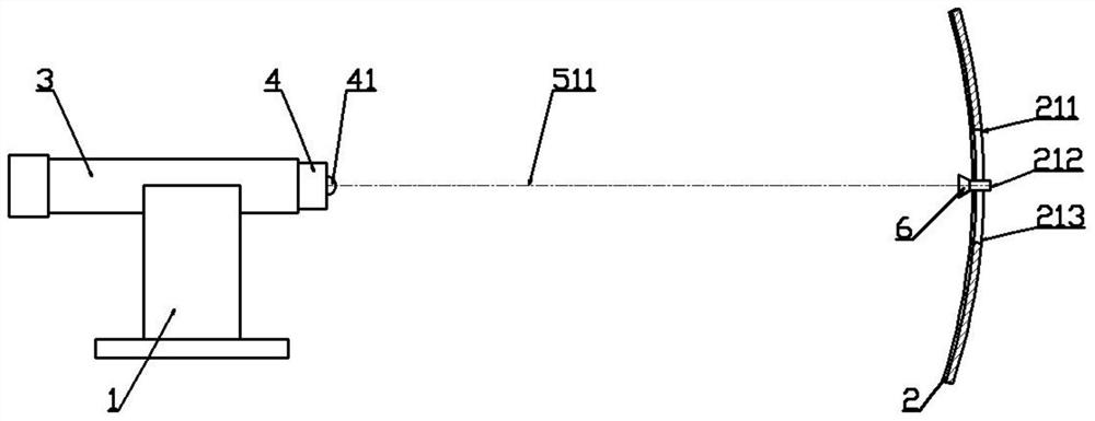
[0024] Such as Figure 1-2 As shown, a missile 3 is installed on the fixed platform 1, and a guidance radar 4 is installed in the warhead of the missile 3. With the launch head 41 of the guidance radar 4 as the center of the sphere, a calibration sphere 2 is provided in front of the guidance radar 4. The spherical surface 2 is provided with an arc-shaped groove 21 perpendicular to the ground plane. The arc-shaped groove 21 is provided with an upper groove 211 located at the upper end, a lower groove 213 located at the lower end and a zero position 212 located in the middle of the groove. The target 6 is installed in the slot 21 .

[0025] Laser alignment device 5 is also installed at the warhead of guided missile 3, and laser alignment device 5 is provid...


PUM


Abstract

A calibration device and a calibration method for aligning the mechanical axis with the electric axis of guidance radar are provided. The invention discloses a calibration device for aligning the mechanical axis with the electric axis of missile guidance radar and a calibration method using the calibration device. The projection of the missile mechanical axis on the zero position of a calibrationsphere is realized through the linear extension of the optical axis. The orientation of a target installed on the zero position is captured through guidance radar, so as to complete the calibration ofthe zero position of the electric axis. The upper and lower threshold measurement values are acquired by moving the target up and down, and thus, the calibration of alignment between the mechanical axis and the electric axis of the missile guidance radar is completed. The influence of system errors such as missile structure deformation and guidance radar installation size deviation on the alignment accuracy of the zero position of the mechanical axis and the zero position of the electric axis is overcome, and the calibration and adjustment of upper and lower threshold values of guidance radaris realized.

Description

technical field [0001] The invention relates to the technical field of radar guidance, in particular to a calibration device and a calibration method for aligning a mechanical axis and an electrical axis of a guidance radar. Background technique [0002] Mechanical parts and electrical parts will have zero drift. For precision equipment, it is necessary to align the mechanical axis with the electrical axis. Alignment calibration at home and abroad is usually to calibrate the mechanical zero position and electrical zero position separately. If there is an installation error or structural deformation in the product assembly, it is difficult to eliminate the error by mechanical zero position calibration and electrical zero position calibration, which will affect to the alignment accuracy of the mechanical and electrical axes in the system. After the existing guidance radar is installed on the missile, only the zero position of the electrical axis of the guidance radar and the ...

Claims


Application Information

Patent Timeline
Patent Type & Authority Patents(China)
IPC IPC(8): G01S7/40G01B11/27F42B15/00F42B15/01
CPCF42B15/00F42B15/01G01B11/27G01S7/4004
Inventor 梁晶晶王海锋苏宇逍孙晓辉付书堂
Owner CHINA AIR TO AIR MISSILE INST
Learn More