
Integrated meter tail structure and electric meter including same

A technology of meter tail and electric meter, which is applied in the direction of measuring electrical variables, measuring devices, instruments, etc., can solve the problems of low welding efficiency, unstable welding quality, and inability to integrate operations, so as to avoid repeated welding, stable welding quality, Addresses the effect of burning hands or products

Pending Publication Date: 2018-05-04
惠州市和瑞龙电器有限公司
View PDF10 Cites 2 Cited by
  • Summary
  • Abstract
  • Description
  • Claims
  • Application Information

AI Technical Summary

Problems solved by technology

This requires the operator to position the leads, and then hold the leads to solder and fix them to the circuit board, and these leads need to be soldered one by one, which cannot be integrated
[0003] In addition, this lead wire welding method has the problems of repeated welding and missing welding, and the welding quality is unstable. While consuming more manpower, the welding work efficiency is also low.

Method used


Image

  • Integrated meter tail structure and electric meter including same
  • Integrated meter tail structure and electric meter including same
  • Integrated meter tail structure and electric meter including same

Examples


Embodiment 1

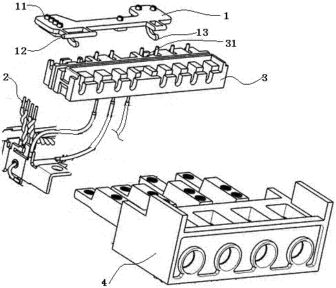
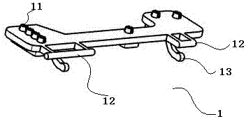
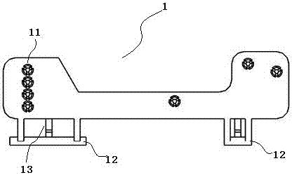
[0031] figure 1 An exploded exploded view of the integrated table tail structure of the present embodiment is given, figure 2 and image 3 The structural schematic diagram and top view of the wire fixing part of this embodiment are respectively given, combined with reference Figure 1~Figure 3 , an integrated tail structure, including a fixed line part 1, a lead wire 2, a first tail part 3 and a second tail part 4, wherein the first tail part 3 is connected and arranged above the second tail part 4, constituting the present The table trailer of the structure.

[0032] As the fixing structure of the lead wire 2, in this embodiment, the wire fixing part 1 is a plate-shaped structure, that is, a wire fixing plate. The wire fixing part 1 includes a wire fixing round hole 11 , a cantilever rod 12 and a buckle 13 . Wherein, the cantilever rod 12 and the buckle 13 are used as the combined parts with the first watch tail part 3, and the cantilever rod 12 and the buckle 13 are loc...

Embodiment 2

[0039] Figure 5 and Figure 6 The exploded exploded view and top view of the electric meter with integrated meter tail structure of this embodiment are respectively given, such as Figure 5 and Figure 6 As mentioned above, in addition to the fixing part 1, the lead wire 2, the first meter tail part 3 and the second meter tail part, the meter also includes a watch case 5, a relay 6, a transformer 7 and a mounting column 8. Wherein, the first watch tail 3 , the second watch tail 4 , the relay 6 and the transformer 7 are fixedly installed in the watch case 5 .

[0040] The external connector of the relay 6 is an in-line terminal 61, which can conveniently realize the connection with components such as a PCB board.

[0041] The relay 6 and the transformer 7 are fixedly connected to the mounting column 8 through the screw 9, and the connection between the two on the mounting column 8 is firm and reliable; the lead wire 2 is respectively drawn from the relay 6 and the transform...


PUM


Abstract

The invention provides an integrated meter tail structure which includes a wire fixing portion, a lead, a first meter tail portion and a second meter tail portion. The wire fixing portion is of a plate-shaped structure provided with a wire fixing round hole, a cantilever rod and a buckle. The lead passes through the wire fixing round hole and is integrally fixed in the wire fixing portion to forma wire concentration area. The wire fixing portion is fixedly connected with the first meter tail portion through the cantilever rod and the buckle, and the first meter tail portion is disposed abovethe second meter tail portion. In the structure, the lead is integrally fixed on the wire fixing portion and forms an integrated structure together with the meter tail portions, to ensure that the position of a component is fixed, so that the lead can be soldered in one time by a wave soldering technology in the same manner as other components, the repeated soldering is avoided, and the productionefficiency of an electric meter is improved. The invention further provides the electric meter with the integrated meter tail structure. The electric meter is simple in structure and convenient to assemble, internal elements are connected firmly, and it is ensured that the electric meter has good overall usability.

Description

technical field [0001] The invention relates to the technical field of electrical instruments, in particular to an integrated meter tail structure and an electric meter containing the structure. Background technique [0002] During the production process of the electric meter, most of the components on the circuit board are welded and fixed by wave soldering. However, some electrical components in the meter, such as relays and current transformers, have lead wires in the form of plastic-covered wires, that is, lead wires are soft lead wires, and the positions of the lead wires are scattered. When these lead wires are fixed, the manual welding method of tin welding is generally adopted. This requires the operator to position the lead wires, and then hold the lead wires to solder and fix them to the circuit board, and these lead wires need to be soldered one by one, which cannot be integrated. [0003] In addition, this lead wire welding method has the problems of repeated w...

Claims


Application Information

Patent Timeline
Patent Type & Authority Applications(China)
IPC IPC(8): G01R11/04
CPCG01R11/04
Inventor 林金镇彭小波
Owner 惠州市和瑞龙电器有限公司
Learn More