Planar transformer with electromagnetic interference compensating function

A planar transformer and electromagnetic interference technology, which is applied in the field of transformers, can solve problems such as the difficulty of adding electromagnetic interference filtering devices, and achieve the effects of preventing electromagnetic interference, suppressing electromagnetic noise, and preventing

Inactive Publication Date: 2018-05-04
SALCOMP SHENZHEN CO LTD
View PDF5 Cites 8 Cited by
  • Summary
  • Abstract
  • Description
  • Claims
  • Application Information

AI Technical Summary

Problems solved by technology

However, limited by space, cost and leakage current required by safety regulations in consumer electronics products, it is difficult to add more EMI filtering devices to compensate for EMI and suppress electromagnetic noise

Method used


Image

  • Planar transformer with electromagnetic interference compensating function
  • Planar transformer with electromagnetic interference compensating function
  • Planar transformer with electromagnetic interference compensating function

Examples


specific Embodiment approach 1

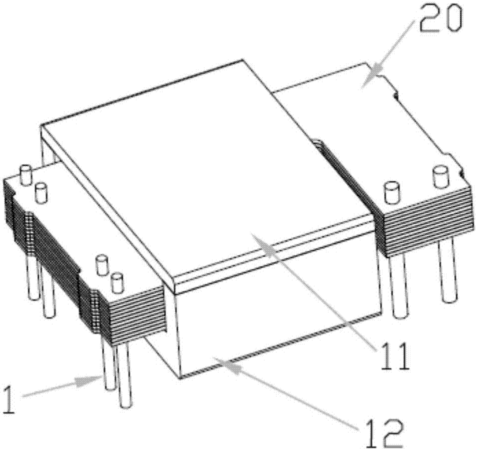
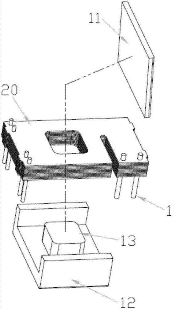
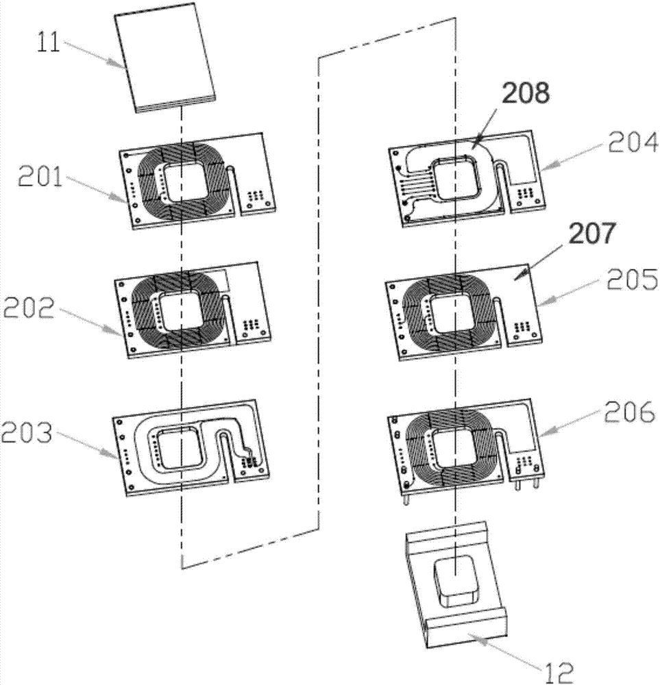
[0025] a kind of like Figure 1~3 The shown planar transformer for compensating electromagnetic interference includes two pairs of magnetic cores that can be assembled with each other, wherein one of the upper magnetic cores is an I-shaped magnetic core 11, and the other lower magnetic core is an E-shaped magnetic core 12, which are assembled on each other. Together to form a magnetic circuit, it also includes an integrated printed circuit board 20 embedded into the E-shaped magnetic core. The integrated printed circuit board 20 is sequentially provided with a primary coil 201 of the primary side of the planar transformer 201, an auxiliary coil 202, and two The secondary coil 203 on the secondary side and the primary coil 206 on the primary side, the primary coil 201 and the primary coil 206 are connected to each other. The pole 13 of the magnetic core passes through the integrated printed circuit board 20 to form a closed magnetic circuit, and also includes a plurality of con...

specific Embodiment approach 2

[0028] The basic composition is the same as the specific embodiment 1, the difference is that the compensation copper clad sheet 207 on the peripheral edge of the electromagnetic interference compensation coil 205 is different in size and shape, such as Figure 4 shown.

specific Embodiment approach 3

[0029] The basic composition is the same as the specific embodiment 1, the difference is that the compensation copper clad sheet 207 on the peripheral edge of the electromagnetic interference compensation coil 205 is different in size and shape, such as Figure 5 shown.


PUM


Abstract

The invention discloses a planar transformer with an electromagnetic interference compensating function. The planar transformer comprises one pair of magnetic cores which can be assembled mutually, wherein one magnetic core is an I type magnetic core while the other magnetic core is an E type magnetic core; the two magnetic cores are assembled together to form a magnetic path; the planar transformer also comprises an integrated printed circuit board embedded in the E type magnetic core; a planar transformer primary side primary coil, an auxiliary coil and a secondary side secondary coil are arranged in the integrated printed circuit board; the planar transformer is characterized in that a planar transformer primary side electromagnetic interference compensating coil is also arranged in theintegrated printed circuit board; the electromagnetic interference compensating coil is arranged between the secondary coil and the primary coil; and compensating copper clad sheets with adjustable areas, sizes and shapes are arranged on the peripheral edge of the electromagnetic interference compensating coil to form distributed capacitance with the secondary coil. By virtue of the planar transformer, electromagnetic interference of the planar transformer can be obviously compensated, electromagnetic noise can be suppressed effectively, and electromagnetic interference to the surrounding precision electronic devices in high-frequency operation can be prevented.

Description

technical field [0001] The invention relates to a transformer, in particular to a planar transformer for compensating electromagnetic interference. Background technique [0002] The transformer is an indispensable and basic component of a switching power supply (Switch Mode Power Supply, abbreviated as SMPS), which is responsible for power transmission and electrical isolation required by electrical safety work regulations (referred to as safety regulations). Among them, the high-frequency transformer can meet the requirements of light, thin and portable power supply because of its small size and light weight. With the development of switching power supply technology and the continuous increase in power density, the requirements for miniaturization and thinning of transformers are getting higher and higher. By printing circuits on printed circuit boards to realize transformer windings and multi-layer stacking, it can make The size of the planar transformer is miniaturized a...

Claims


Application Information

Patent Timeline
Patent Type & Authority Applications(China)
IPC IPC(8): H01F27/28H01F27/33H01F27/36H01F27/38H01F27/40
CPCH01F27/36H01F27/2804H01F27/33H01F27/38H01F27/40H01F2027/2809H01F2027/2819
Inventor 廖忠明劳里·普拉宁
Owner SALCOMP SHENZHEN CO LTD
Why Eureka
Try Eureka