Sample injector and microfluidic system

A technology of microfluidic control system and sample injector, which is applied in the direction of laboratory equipment, fluid controllers, and laboratory containers, etc. Stable sample, high injection precision, easy to clean

Active Publication Date: 2018-05-08
广东永诺医疗科技有限公司
View PDF8 Cites 10 Cited by
  • Summary
  • Abstract
  • Description
  • Claims
  • Application Information

AI Technical Summary

Problems solved by technology

[0003] For now, the structure and operation of the existing liquid path sampli

Method used


Image

  • Sample injector and microfluidic system
  • Sample injector and microfluidic system
  • Sample injector and microfluidic system

Examples


Embodiment Construction

[0036] The present invention will be described in further detail below in conjunction with the accompanying drawings and specific embodiments.

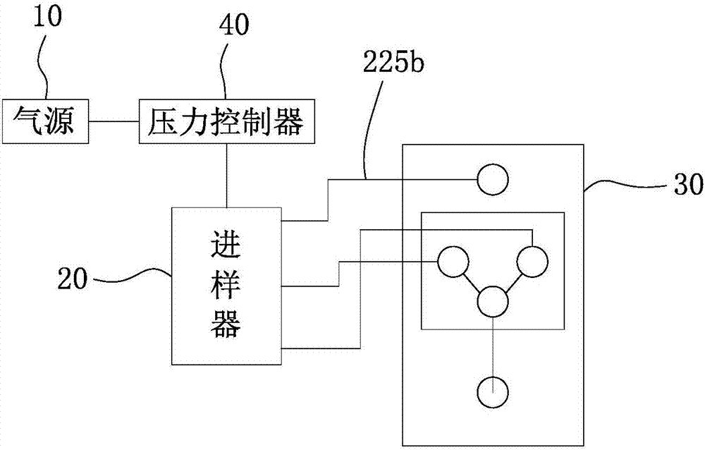
[0037] Such as figure 1 As shown, this embodiment provides a microfluidic system, including a gas source 10 , at least one sample injector 20 and a microfluidic chip 30 . The gas source 10 is connected to the sampler 20 , and the microfluidic chip 30 is connected to the sampler 20 . The high-pressure gas generated by the gas source 10 flows into the sampler 20 , and the high-pressure gas pushes the sample fluid in the sampler 20 out to the microfluidic chip 30 . The microfluidic chip 30 performs operations such as analysis, mixing, droplet generation, and cell encapsulation on the sample fluid.

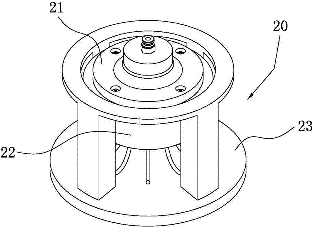
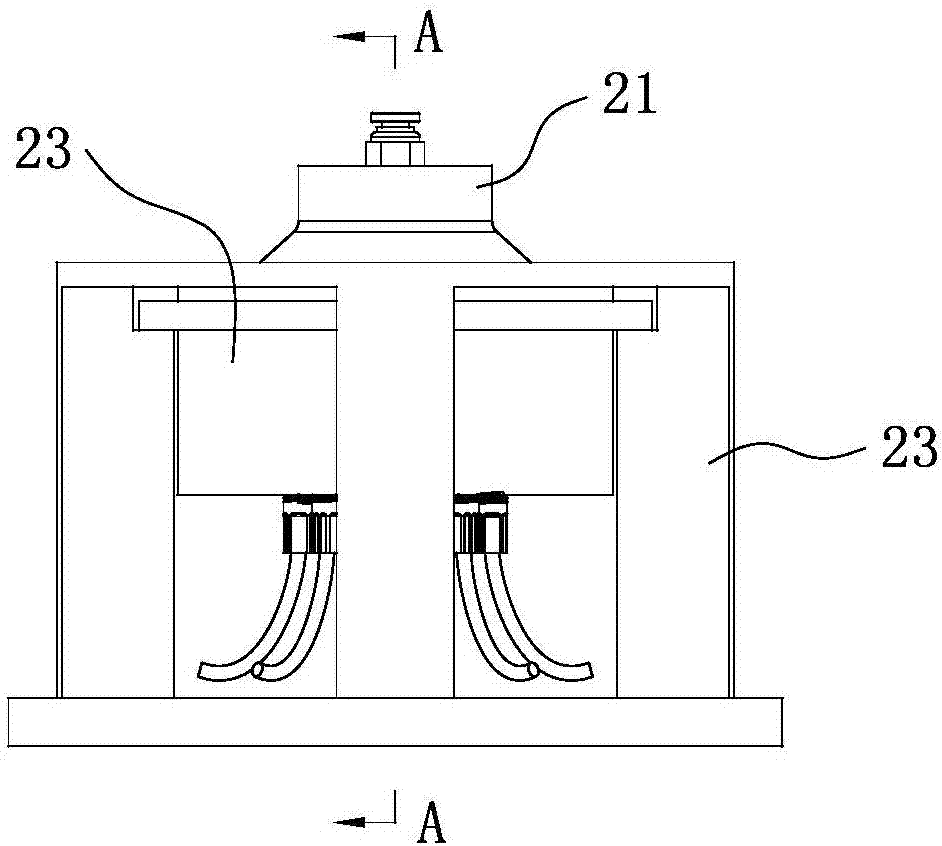
[0038] refer to Figure 2 to Figure 3 , The injector 20 includes an upper cover 21 , a lower housing 22 and a support seat 23 . The lower casing 22 is detachably installed on the supporting seat 23 . The upper cover 21 is sealed and deta...


PUM


Abstract

The invention relates to the technical field of analysis equipment of biology, chemistry and the like, in particular to a sample injector. The sample injector includes an upper cover, a lower shell and a support base; the lower shell is mounted on the support base; an open sample injection cavity is formed in the end, away from the support base, of the lower shell; the upper cover covers and sealsan opening of the sample injection cavity; an air inlet is formed in the upper cover and is communicated with the sample injection cavity, and a plurality of sample cells are arranged in the sample injection cavity and are uniformly distributed in the sample injection cavity. The sample injector has the advantage that the sample cells are arranged in the sample injection cavity. Needed sample fluid is injected into each sample cell, the air inlet is connected with an air source, and airpressure generated by the air source extrudes the sample fluid out of the sample sells; the sample cells areuniformly distributed in the sample injection cavity, and the air pressure enters the sampleinjection cavity from the air inlet is uniformly distributed in the sample cells so that the sample fluid in each sample cell can be stably extruded out, and not only is fluid sample injection stable, but also the accuracy is high.

Description

technical field [0001] The invention relates to the technical field of analysis equipment such as biology and chemistry, in particular to a sample injector and a microfluidic control system thereof. Background technique [0002] Microfluidic systems perform operations such as preparation, reaction, separation, and detection of fluids in the micro-nano scale space. The microfluidic system mainly includes a microfluidic chip, a liquid sampling system and a detection system. The liquid sampling system is used to inject samples into microscopic microfluidic chips for analysis. [0003] For now, the structure and operation of the existing liquid path sampling system are complicated, and the stability and accuracy of sampling are poor. Contents of the invention [0004] Based on this, it is necessary to provide a sample injector and its microfluidic system with stable sample injection and high sample injection accuracy for the above technical problems. [0005] In order to ac...

Claims


Application Information

Patent Timeline
IPC IPC(8): B01L3/00
CPCB01L3/50273B01L2200/10B01L2400/0481Y02A50/30
Inventor 梁帅刘伟李冬梅何关金廖丽敏王姗姗
Owner 广东永诺医疗科技有限公司
Why Eureka
Try Eureka