
Mechanical stirring device for buildings

A technology for mechanical mixing and construction, which is applied to cement mixing devices, clay preparation devices, cleaning methods and appliances, etc. It can solve problems such as the deformation of the stirring shaft, the stress of the stirring shaft, and the impact on the mixing quality, so that it is not easy to deform and reduce the impact. , Improve the effect of rigidity

Inactive Publication Date: 2018-05-08
绍兴韵足针纺织有限公司
View PDF0 Cites 5 Cited by
  • Summary
  • Abstract
  • Description
  • Claims
  • Application Information

AI Technical Summary

Problems solved by technology

[0005] In view of the deficiencies in the prior art, the present invention provides a mechanical stirring device for construction, which solves the problem that most of the mechanical stirring devices for construction currently used in the market mentioned above stir the materials by driving the stirring shaft. Protective device, due to the high density of the material, it is easy to cause the stirring shaft to be stressed. When it is stirred by the stirring shaft for a long time, it is easy to cause the deformation of the stirring shaft, thus affecting the quality of the stirring

Method used


Image

  • Mechanical stirring device for buildings
  • Mechanical stirring device for buildings
  • Mechanical stirring device for buildings

Examples


Embodiment Construction

[0031] The following will clearly and completely describe the technical solutions in the embodiments of the present invention with reference to the accompanying drawings in the embodiments of the present invention. Obviously, the described embodiments are only some, not all, embodiments of the present invention. Based on the embodiments of the present invention, all other embodiments obtained by persons of ordinary skill in the art without making creative efforts belong to the protection scope of the present invention.

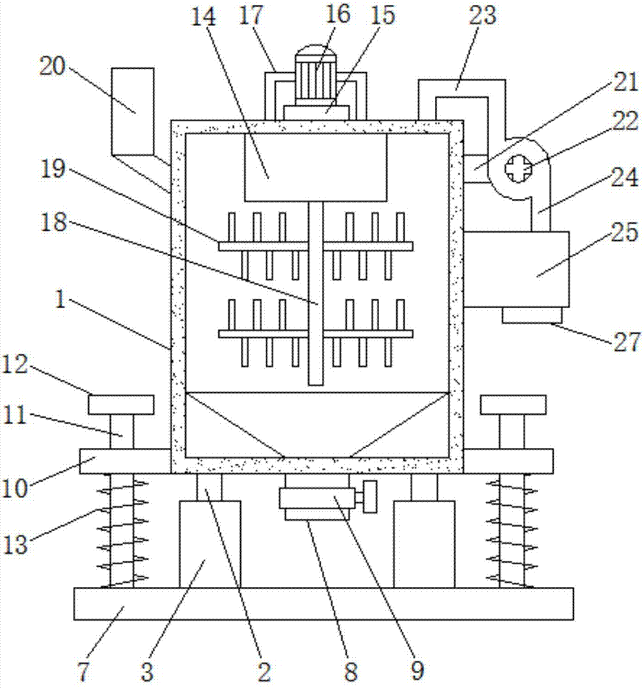
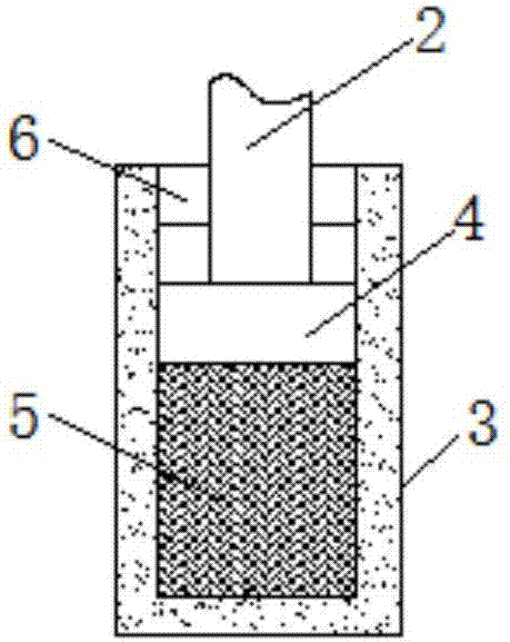
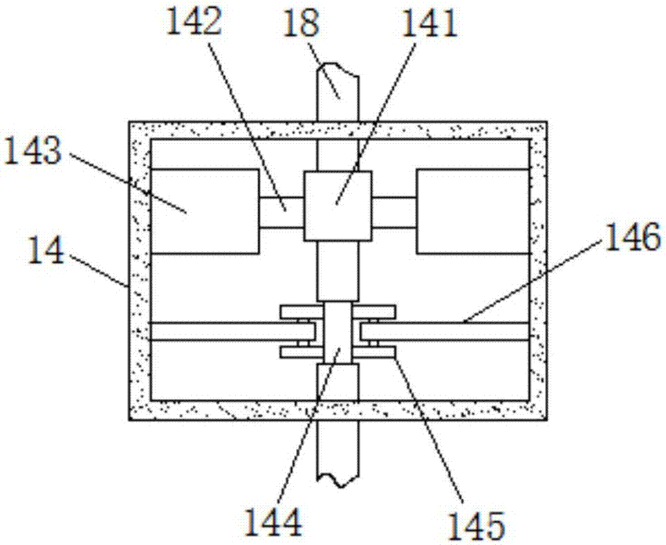
[0032] Embodiments of the present invention provide a mechanical stirring device for construction, such as Figure 1-5 As shown, including the box body 1, the four corners at the bottom of the box body 1 are fixedly connected with the top of the pressure rod 2, and the bottom end of the pressure rod 2 runs through the shock absorber 3 and extends to the inside of the shock absorber 3 and the top of the pressure block 4 Fixedly connected, the opening of the sho...


PUM


Abstract

The invention provides a mechanical stirring device for buildings, relating to the field of a stirring device. The mechanical stirring device comprises a box body, and the four corners of the bottom of the box body are fixedly connected with the top end of a press rod. The bottom end of the press rod penertates through a shock absorber and extends to the inner part of the shock absorber to be fixedly connected with the top of a press block, hydraulic oil is arranged in the shock absorber and is positioned at the bottom of the press block, and the bottom of the shock absorber is fixedly connected with the top of the press block. A discharge hopper is arranged in the box body, the bottom of the discharge hopper penertates through the box body and extends to the lower part of the box body, and a discharge valve is arranged on the surface of the discharge hopper and is positioned at the bottom of the box body. When a motor drives a rotation shaft to rotate, a fixing sleeve is fixed througha stabilizer in a stable box, and the rotation shaft slides along a concave ring groove through a roller. Therefore, the rotation shaft is effectively protected and is not easy to deform, and the impact on the stirring quality is effectively reduced.

Description

technical field [0001] The invention relates to the technical field of stirring devices, in particular to a mechanical stirring device for construction. Background technique [0002] Stirring is a kind of circulation through the stirrer, so that the gas, liquid and even suspended particles in the solution can be mixed evenly. In order to achieve this goal, it needs to be realized by means of forced convection and uniform mixing, that is, the internal components of the agitator. When stirring the mixture, the density difference, viscosity and interfacial tension of the two phases have a great influence on the stirring operation. The smaller the density difference and the interfacial tension, the easier it is for the system to achieve stable dispersion; the higher the viscosity, the more unfavorable it is to form a good circulation flow and sufficient turbulent pulsation, and consume more stirring power. With the rapid development of the construction industry, the use of con...

Claims


Application Information

Patent Timeline
Patent Type & Authority Applications(China)
IPC IPC(8): B28C5/16B08B15/04
CPCB28C5/16B08B15/04B28C5/0806B28C5/0831B28C5/0856
Inventor 孙巧萍俞小红
Owner 绍兴韵足针纺织有限公司
Learn More