
Real-time liquid level tracking control method for hydraulic station of hot continuous rolling temper unit

A technology of tracking control and hydraulic station, applied in metal rolling, metal rolling, mechanical equipment, etc., can solve problems such as unreasonable alarm settings, failure to monitor oil spills in time, energy waste, etc., and achieve good market promotion value and Reasonable foreground and alarm settings and strong operability

Inactive Publication Date: 2018-05-08
PANGANG GRP PANZHIHUA STEEL & VANADIUM
View PDF8 Cites 7 Cited by
  • Summary
  • Abstract
  • Description
  • Claims
  • Application Information

AI Technical Summary

Problems solved by technology

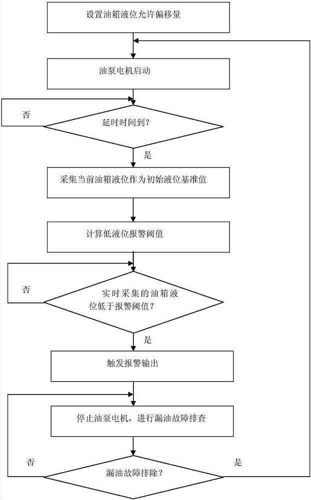
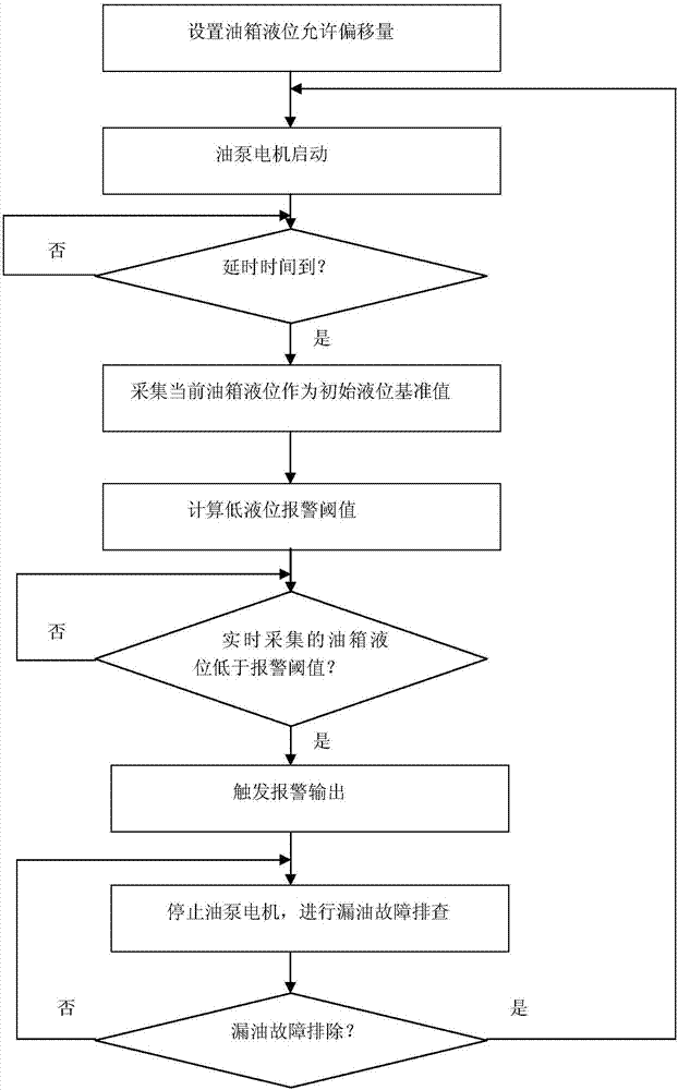
[0005] The technical problem to be solved by the present invention is: to propose a real-time liquid level tracking control method for the hydraulic station of the tempering unit in the hot continuous rolling, so as to solve the unreasonable alarm setting in the liquid level control scheme of the hydraulic station of the tempering unit in the traditional technology, and the inability to monitor oil leakage in time events, which are likely to cause energy waste

Method used


Image

  • Real-time liquid level tracking control method for hydraulic station of hot continuous rolling temper unit
  • Real-time liquid level tracking control method for hydraulic station of hot continuous rolling temper unit

Examples


Embodiment Construction

[0026] The present invention aims to propose a real-time liquid level tracking control method for the hydraulic station of the tempering unit in the hot continuous rolling, so as to solve the unreasonable alarm setting in the liquid level control scheme of the hydraulic station of the tempering unit in the traditional technology, and the failure to monitor the oil leakage event in time, which is easy to cause energy loss. waste problem.

[0027] The core idea of ​​the present invention is: by setting the allowable deviation of the liquid level of the hydraulic station as the allowable oil leakage, use the storage function of the hydraulic system PLC to record the initial liquid level value after the hydraulic system oil pump is started for one minute, and use the initial liquid level The low liquid level alarm threshold of the hydraulic system alarm is obtained by subtracting the allowable oil leakage from the numerical value; during the operation of the system, the liquid leve...


PUM


Abstract

The invention relates to liquid level tracking control techniques for hydraulic stations in the hot continuous rolling field and discloses a real-time liquid level tracking control method for a hydraulic station of a hot continuous rolling temper unit. By adoption of the real-time liquid level tracking control method for the hydraulic station of the hot continuous rolling temper unit, the problemsthat according to a liquid level control scheme for a hydraulic station of a temper unit in the prior art, alarm setting is unreasonable, oil leakage events cannot be monitored in time, and energy waste is likely to be caused are solved. According to the real-time liquid level tracking control method for the hydraulic station of the hot continuous rolling temper unit, the permissible liquid leveldeviation value of the hydraulic station is set as the permissible oil leakage quantity, an initial liquid level numerical value is recorded by means of the storage function of a PLC of a hydraulic system after an oil pump of the hydraulic system operates for one minute, and a low liquid level alarm threshold value for alarming of the hydraulic system is obtained by subtracting the permissible oil leakage quantity from the initial liquid level numerical value; and in the operating process of the system, the liquid level of an oil tank of the hydraulic station is acquired in real time and compared with the low liquid level alarm threshold value, and when the real-time liquid level of the oil tank of the hydraulic station is smaller than the low liquid level alarm threshold value, alarm output is triggered to remind an operator to stop a hydraulic pump or to stop the hydraulic pump automatically, and thus the situation that a large quantity of hydraulic oil leaks is avoided.

Description

technical field [0001] The invention relates to a hydraulic station liquid level tracking control technology in the field of hot continuous rolling, in particular to a real-time liquid level tracking control method for a hydraulic station of a hot continuous rolling skin pass unit. Background technique [0002] The hydraulic station of the tempering unit is the hydraulic equipment of the leveling and decoiling unit (such as walking beam conveyor, steel coil trolley, pinch roller, five-roll straightening machine, slitting shear, uncoiler, rewinding machine, coiler, strip pressing Rolls, etc., as well as the auxiliary action of the tempering machine and the roll changing device) provide hydraulic power sources. The system is composed of oil tank, main oil pump, circulation pump, accumulator, cooler, valve table and executive components. The fuel tank of the hydraulic station is equipped with an analog liquid level sensor for continuous measurement of the liquid level of the f...

Claims


Application Information

Patent Timeline
Patent Type & Authority Applications(China)
IPC IPC(8): F15B20/00B21B33/00
CPCF15B20/005B21B33/00
Inventor 田景钢胡学忠周昊王耀黄建平唐家杨周睿陈建波
Owner PANGANG GRP PANZHIHUA STEEL & VANADIUM
Learn More