Heat-shielding structure of steering engine

A steering gear and heat protection technology, which is applied in the direction of projectiles, offensive equipment, weapon types, etc., can solve the problems of large space occupied by the heat insulation layer, unsatisfactory heat protection effect, high coating spraying temperature, etc., to achieve effective heat isolation, Small footprint and low material cost

Active Publication Date: 2018-05-08
北京威标至远科技发展有限公司
View PDF9 Cites 6 Cited by
  • Summary
  • Abstract
  • Description
  • Claims
  • Application Information

AI Technical Summary

Problems solved by technology

The heat protection inside the cabin is generally realized by heat-insulating coating or thick heat-insulating material. The spraying temperature of the coating is high, and the heat-insulating layer takes up a large space; Thermal protection is not ideal

Method used


Image

  • Heat-shielding structure of steering engine
  • Heat-shielding structure of steering engine
  • Heat-shielding structure of steering engine

Examples


Embodiment 1

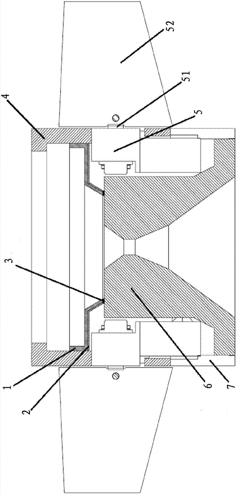
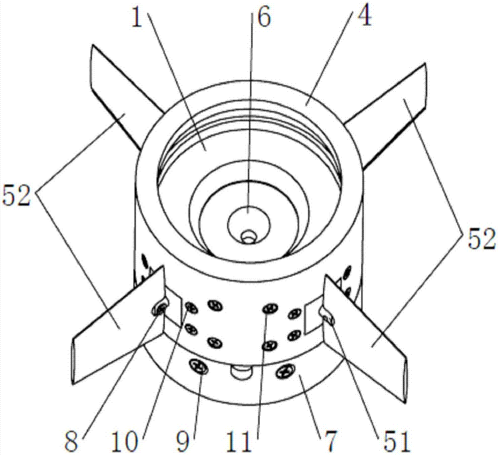
[0039] figure 1 A longitudinal sectional view of an embodiment of a target missile installed with a steering gear heat-proof structure of the present invention is shown, figure 2 is a full perspective view of the embodiment. The target projectile has structural elements of the body shell 4, steering gear 5, rudder shaft 51, steering surface 52, tail nozzle 6 and engine casing 7, and the steering gear 5 is fixed on the body shell 4, tail nozzle In the sealed cavity surrounded by the tube 6, the engine casing 7, and the heat-proof structure of the steering gear. The inner surface of the rear section of the engine housing 7 and the outer surface of the front section of the tail nozzle 6 are connected by large threads, the rear section of the engine housing 7 and the front section of the body casing 4 are connected by screws 29 distributed along the radial direction, and the body casing 4 It is connected with the steering gear 5 through three screws 10 distributed radially, and...

Embodiment 2

[0042] Embodiment 2. Simulation analysis of heat insulation effect

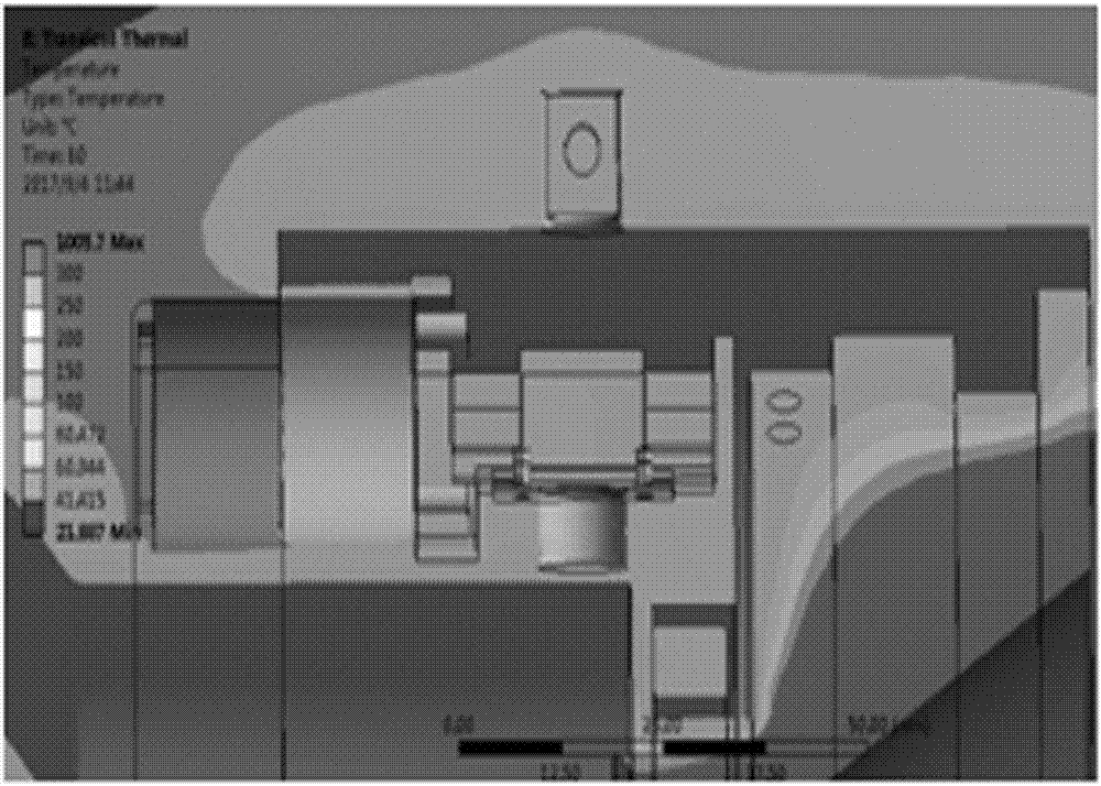
[0043] Use Ansys to simulate the heat insulation effect of the steering gear shield. The thickness of the steel plate in the simulation model is 2mm. The outer surface temperature caused by aerodynamic heating is set to 85°C, the engine tail flame temperature is 1000°C, and the tail nozzle outer surface temperature is 90°C. The temperature transfer of the surrounding environment of the steering gear with and without the steering gear shield is studied. The simulation results are shown in image 3 and Figure 4 . The irregular curves in the figure are the edges of different temperature ranges, and the darker the color, the higher the temperature. It can be seen from the figure that the tail nozzle flame heat is completely isolated outside the protective cover (see image 3 The dark area on the right), which reduces the risk of the tailpipe flame heat affecting the normal operation of the servo.


PUM


Abstract

The invention discloses a heat-shielding structure of a steering engine. The structure is in a truncated inverted conical barrel shape, the top of the inverted conical barrel is defined as the front section, the bottom is defined as the back section, the inner circumferential surface of the inverted conical barrel is an outer isolating surface comprising a steel plate 1 and is used for separatingheat radiated to the steering engine 5 by flames ejected backwards by an exhaust nozzle 6, the outer circumferential surface is a connecting surface comprising an asbestos pad 2, the connecting surface extends from the back section to the front section to be in sealed connection with a projectile shell 4, the steering engine 5 and the exhaust nozzle 6 respectively, and the structure is placed in atruncated inverted conical barrel cavity, defined by the projectile shell 4, the steering engine 5, the exhaust nozzle 6 and an engine shell 7, at the tail of the engine. With the structure, branching and ejection of tail flames of the engine are facilitated, radiation of the tail flames of the engine, backflow heating and bottom environment pressure directly act on the heat-shielding structure,the structure is simple and reliable, and materials are cheap and easy to obtain.

Description

technical field [0001] The invention relates to a steering gear heat protection structure, which belongs to the technical field of steering gear heat protection. Background technique [0002] The steering gear is the actuator of the missile control system and is installed inside the missile body. In some cases, the steering gear is still close to the exhaust nozzle of the engine. At this time, the steering gear needs thermal protection, because the exhaust flame of the engine has the characteristics of high temperature, high pressure and high enthalpy. The machine is burned. The heat protection inside the cabin is generally realized by heat-insulating coating or thick heat-insulating material. The spraying temperature of the coating is high, and the heat-insulating layer takes up a large space; Thermal protection is not ideal. In order to solve the above problems, it is necessary to design a heat-proof structure that can be connected to the missile body. This heat-proof s...

Claims


Application Information

Patent Timeline
Patent Type & Authority Applications(China)
IPC IPC(8): F42B10/64
CPCF42B10/64
Inventor 孙国权滕涛廖云飞赵小花
Owner 北京威标至远科技发展有限公司
Why Eureka
Try Eureka