Method for measuring deviation between mechanical center of rectangular beam transmitting device and beam center

A technology of beam emission and rectangular shape, which is applied in the field of optical measurement, can solve the problems that it is not easy to adjust the mechanical center to adjust the outgoing beam, and the spatial position of the outgoing beam is difficult to determine, and achieve the effects of performance improvement, simple equipment structure, and convenient operation

Active Publication Date: 2018-05-08
HUBEI JIUZHIYANG INFRARED SYST CO LTD
View PDF12 Cites 0 Cited by
  • Summary
  • Abstract
  • Description
  • Claims
  • Application Information

AI Technical Summary

Problems solved by technology

If the center of the outgoing beam does not coincide with the mechanical center, it is difficult to determine the spatial position of the outgoing beam first, and it is not easy to adjust the position of the outgoing beam by adjusting the mechanical center

Method used


Image

  • Method for measuring deviation between mechanical center of rectangular beam transmitting device and beam center

Examples


Embodiment Construction

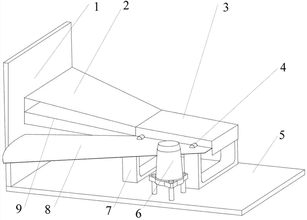
[0016] Provide the specific embodiment of the test device that uses the method of the present invention to build below in conjunction with accompanying drawing, as figure 1 Shown:

[0017] The invention discloses a method for measuring the deviation between the mechanical center and the beam center of a rectangular beam emitting device with a laser level, figure 1 Shown is a basic embodiment of the test device built using the method of the present invention, the test device comprises a rectangular beam emitting device 3, comprising a first support system 5 and a second support system 7 of the rectangular beam emitting device 3, comprising A laser level 6 for indicating the height of the front and rear axis 4 of the rectangular beam emitting device 3, which also provides a laser level 8 for the rectangular beam 2 for reference; includes a vertical plate 1 for receiving the rectangular beam 2 and the laser level 8.

[0018] Such as figure 1 As shown, the rectangular beam emitt...


PUM


Abstract

The invention discloses a method for measuring the deviation between the mechanical center of a rectangular beam emitting device and the beam center, including the following steps: a vertical plate, asecond support system and a laser leveler are set; the anterior-posterior shaft of a rectangular beam emitting device is fixed on the second support system; with the plane where the center line of the anterior-posterior shaft of the rectangular beam emitting device is located as the mechanical center, the laser horizontal line of the laser leveler is projected to the anterior-posterior shaft, andthe height of the anterior-posterior shaft is adjusted to make the center line of the anterior-posterior shaft all on the laser horizontal line; the rectangular beam emitting device emits a rectangular beam and projects the rectangular beam to the vertical plate, the beam center is measured by measuring the upper and lower edges of the rectangular beam, and the beam center and the laser horizontal line are compared to obtain the deviation between the mechanical center of the rectangular beam emitting device and the beam center. The measuring method is convenient to operate, and the equipmentis simple. The deviation between the mechanical center of the rectangular beam emitting device and the beam center can be effectively measured. The method is of great significance to improving the performance of the rectangular beam emitting device.

Description

technical field [0001] The patent of the invention belongs to the technical field of optical measurement, and specifically relates to a method for measuring the deviation between the mechanical horizontal center of a rectangular beam emitting device and the horizontal center of the beam. Background technique [0002] In some specific occasions, it is necessary to use rectangular beams to achieve specific technical goals. [0003] The rectangular beam emitting device is a light source device capable of emitting a beam with a rectangular beam cross-section, and is usually installed in other mechanical systems through an external mechanical interface. [0004] The rectangular beam emitting device is generally installed through its mechanical center. If the center of the rectangular beam emitted by the rectangular beam emitting device deviates from its mechanical center, it will be difficult to control the outgoing beam by controlling the installation position, which will bring ...

Claims


Application Information

Patent Timeline
Patent Type & Authority Applications(China)
IPC IPC(8): G01B11/26
CPCG01B11/26
Inventor 王波洪普董广坤熊涛吴耀胡栋
Owner HUBEI JIUZHIYANG INFRARED SYST CO LTD
Why Eureka
Try Eureka