
Liquid Crystal Display Device

A liquid crystal display device, liquid crystal panel technology, applied in optics, instruments, nonlinear optics, etc., can solve problems such as image Stokes shift, retinal damage, visual distortion, etc., to improve visual sensitivity and visibility Effect

Active Publication Date: 2018-05-08
LG DISPLAY CO LTD
View PDF8 Cites 9 Cited by
  • Summary
  • Abstract
  • Description
  • Claims
  • Application Information

AI Technical Summary

Problems solved by technology

However, this results in a Stokes shift of the image from the liquid crystal display device, resulting in visual (color) distortion
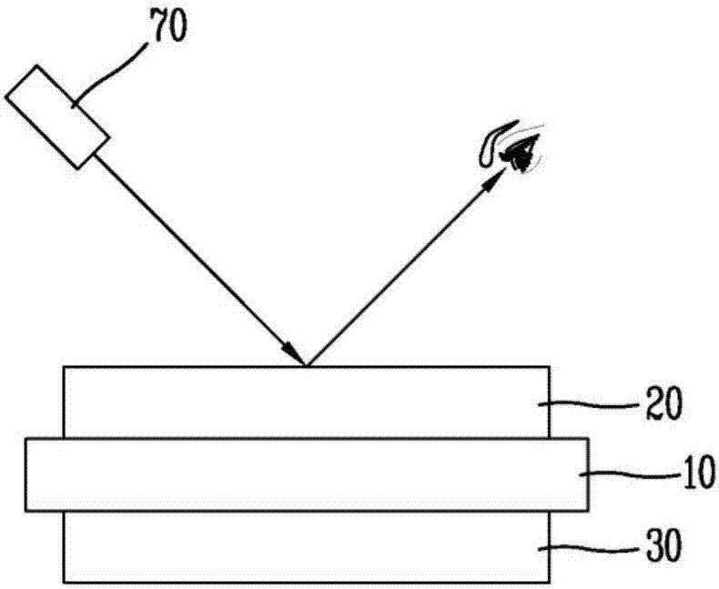
[0018] Specifically, when a near-ultraviolet laser pointer is applied, if the user's eyes are directly / indirectly exposed to ultraviolet light having a wavelength near 405nm, which is short-wavelength visible light with high energy, the retina may be damaged

Method used


Image

  • Liquid Crystal Display Device
  • Liquid Crystal Display Device
  • Liquid Crystal Display Device

Examples


Embodiment Construction

[0039] Exemplary embodiments of a liquid crystal display device according to the present disclosure will be described more fully hereinafter with reference to the accompanying drawings so that those skilled in the art can easily carry out the exemplary embodiments of the present disclosure.

[0040] In this disclosure, as an example, a liquid crystal display device will be described. However, the present disclosure is not limited thereto, but can also be applied to light-emitting display devices such as electroluminescence (EL) elements, light-emitting diodes (LEDs), vacuum fluorescent display devices (VFDs), field emission displays (FEDs), and Plasma Display Panel (PDP)) and non-luminescent display devices.

[0041] The advantages and features of the present disclosure and a method of achieving the advantages and features will be apparent by referring to the exemplary embodiments described in detail below and the accompanying drawings. However, the present disclosure is not ...


PUM


Abstract

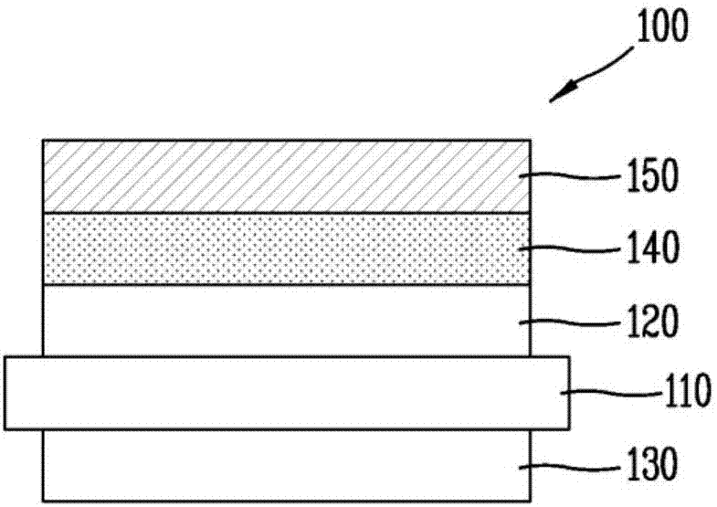
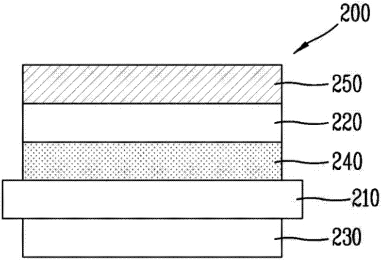
The present disclosure provides a liquid crystal display device including a light source unit which supplies light to a liquid crystal panel, a lower polarizing plate disposed below the liquid crystalpanel, an upper polarizing plate, a light absorption filter, and a fluorescent filter disposed above the liquid crystal panel. According to the present disclosure, when a laser pointer in a visible ray region illuminates after implementing a display image, light irradiated by the laser is absorbed by the fluorescent filter and the light absorption filter to convert the light into red, green, andblue light to be emitted, thereby improving visibility in accordance with illumination of a laser pointer.

Description

[0001] Cross References to Related Applications [0002] This application claims priority from Korean Patent Application No. 10-2016-0143648 filed on October 31, 2016 at the Korean Intellectual Property Office, the disclosure of which is incorporated herein by reference. technical field [0003] The present invention relates to a display device, and more particularly, to a liquid crystal display device that can improve visibility with respect to irradiation of a laser pointer in a visible ray region after displaying an image is realized. Background technique [0004] In the recent information society, the importance of display devices as visual information transmission media has been further emphasized. Therefore, in order to occupy a dominant position in the future, display devices need to satisfy requirements such as low power consumption, small thickness, light weight, and high image quality. [0005] Display devices can be divided into: self-luminous light-emitting type...

Claims


Application Information

Patent Timeline
Patent Type & Authority Applications(China)
IPC IPC(8): G02F1/1335
CPCG02F1/133514G02F1/133509G02F2201/08G02F1/133562G02F1/133528G02B27/20G02F1/1351G02F2202/046G02F1/133614G02F1/133621
Inventor 金玄升鱼润净
Owner LG DISPLAY CO LTD
Learn More