
Power supply control device and control characteristic correction data generation method for power supply control device

A technology of power supply control and current detection resistance, which is used in computer control, transmission control, general control system, etc.

Inactive Publication Date: 2018-05-08
MITSUBISHI ELECTRIC CORP
View PDF8 Cites 4 Cited by
  • Summary
  • Abstract
  • Description
  • Claims
  • Application Information

AI Technical Summary

Problems solved by technology

[0009] In addition, when the current detection resistor is installed on the downstream side of the inductive load, although there is an advantage that the differential amplifier is not required and the fluctuation error of the power supply voltage Vb does not need to be corrected, there is a wiring problem for one inductive load. Compared with the disadvantages of both upstream wiring and downstream wiring, when the current detection resistor is installed on the upstream side of the inductive load, there is an advantage that the downstream wiring can be connected through the vehicle body and thus omitted.

Method used


Image

  • Power supply control device and control characteristic correction data generation method for power supply control device
  • Power supply control device and control characteristic correction data generation method for power supply control device
  • Power supply control device and control characteristic correction data generation method for power supply control device

Examples


Embodiment approach 1

[0084] Detailed Description of Embodiment 1

[0085] (1) Detailed description of the structure

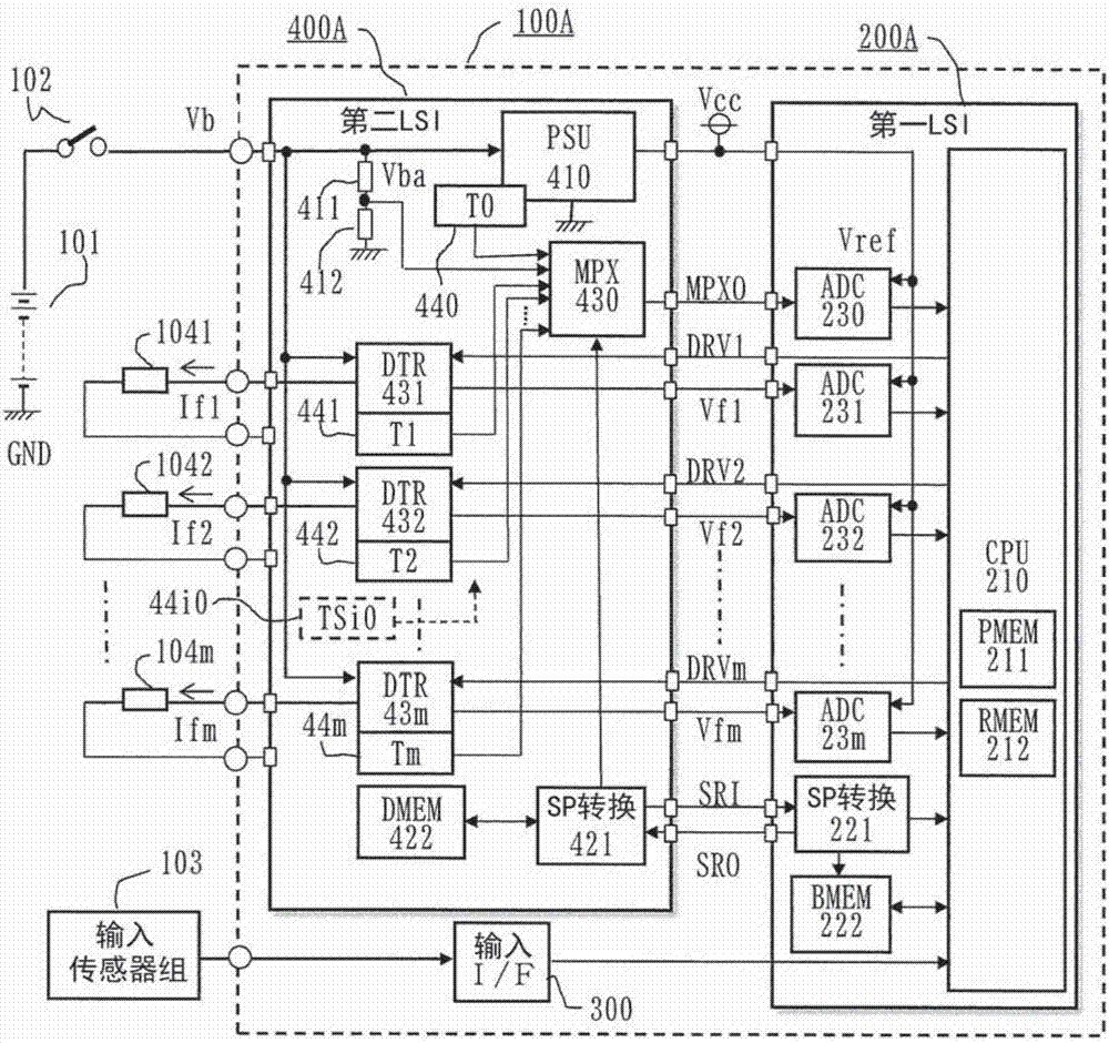
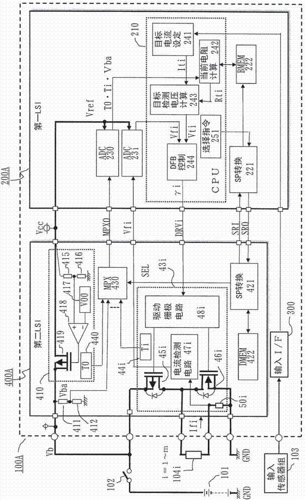
[0086] Next, the overall circuit block diagram of the power supply control device according to Embodiment 1 of the present invention is figure 1 , and involving figure 1 A detailed circuit block diagram of a power supply circuit part of the device is figure 2 , to describe its structure in detail.

[0087] first, figure 1 Among them, the power supply control device 100A, for example, supplies the inductive loads 104i (i=1, 2... The load current Ifi varies, and the power supply voltage Vb is applied from the DC power supply 101 as the vehicle battery via the output contact 102 of the power relay that is biased when the current switch not shown is closed.

[0088] The power supply control device 100A is composed of a first integrated circuit element 200A and a second integrated circuit element 400A, the first integrated circuit element 200A is mainly composed of a microprocesso...

Embodiment approach 2

[0278] Detailed Description of Embodiment 2

[0279] (1) Detailed description of the structure

[0280] Next, the overall circuit block diagram of the power supply control device according to Embodiment 2 of the present invention is Figure 7 , and involving Figure 7 A detailed circuit block diagram of a power supply circuit part of the device is Figure 8 , with figure 1 , figure 2 The structure will be described in detail centering on the different points of the device.

[0281] in addition, figure 1 , figure 2 The device of the first integrated circuit element 200A carries out the negative feedback control for the load current Ifi through the microprocessor 210 in the first integrated circuit element 200A, with respect to this, Figure 7 , Figure 8 The main difference of the device is that it is controlled by the negative feedback control circuit 49i provided in the second integrated circuit element 400B, and then the microprocessor 210 in the first integrated c...

Embodiment approach 3

[0367] Detailed Description of Embodiment 3

[0368] (1) Detailed description of the structure

[0369] Next, the overall circuit block diagram of the power supply control device according to Embodiment 3 of the present invention is Figure 11 , and design Figure 11 A detailed circuit block diagram of a power supply circuit part of the device is Figure 12 , with figure 1 , figure 2 The structure will be described in detail centering on the different points of the device.

[0370] in addition, figure 1 , figure 2 The device of the first integrated circuit element 200A carries out the negative feedback control for the load current Ifi through the microprocessor 210 in the first integrated circuit element 200A, with respect to this, Figure 11 , Figure 12 The device does not perform negative feedback control, and uses the load resistance Rci calculated by the current load resistance calculation unit 247 provided in the first integrated circuit element 200C, and uses ...


PUM


Abstract

The invention provides a power supply control device which corresponds with environment changes such as individual offset change, ambient temperature and power supply voltage of an application component and performs high-precision current control in low cost. Correction coefficients corresponding to parameters by which characteristic variation is caused are stored in a data memory (422) of a second integrated circuit element (400A) in which driving open / close elements (45i) respectively connected in series to a plurality of inductive loads (104i) are integrated, and a first integrated circuitelement (200A) that cooperates with the second integrated circuit element suppresses a current control error accompanying individual variation among circuit components and environmental temperature variation by reading present values of the parameters and combining the present values with the correction coefficients. The correction coefficients are calculated by an adjustment tool in a state wherethe second integrated circuit element (400A) is provided singly, and therefore correction data can be generated in relation to a plurality of temperature environments easily.

Description

technical field [0001] The present invention relates to a power supply control device that individually supplies variable load currents to a plurality of inductive loads, and a method for correcting fluctuations in control characteristics caused by individual deviations of circuit components and temperature fluctuations applied to the power supply control device Improvements to the calibration data generation method. Background technique [0002] For example, in the automatic transmission of an automobile, 3 to 6 proportional solenoid valves are used in order to select multiple gears, and it is required to use various target currents to control the energization of one or more proportional solenoid coils (linear solenoid coils) at the same time. And by controlling the energization duty ratio of the power supply switching element connected in series with each proportional electromagnetic coil, high-precision current control matching the target current is performed. [0003] A...

Claims


Application Information

Patent Timeline
Patent Type & Authority Applications(China)
IPC IPC(8): G05F1/56
CPCG05F1/561H02M3/158F16H61/0006F16H2061/005H02M1/0006H02M1/0009H02M1/327F16H61/0251F16H2061/0255G05B15/02H02M1/08
Inventor 矢内隆之
Owner MITSUBISHI ELECTRIC CORP
Learn More