
Method for manufacturing millimeter-wave radar PCB

A technology of millimeter wave radar and manufacturing method, which is applied to the removal of conductive materials by chemical/electrolytic methods, multi-layer circuit manufacturing, electrical components, etc., can solve problems such as inability to realize SMT graphics

Inactive Publication Date: 2018-05-08
SHENNAN CIRCUITS
View PDF5 Cites 4 Cited by
  • Summary
  • Abstract
  • Description
  • Claims
  • Application Information

AI Technical Summary

Problems solved by technology

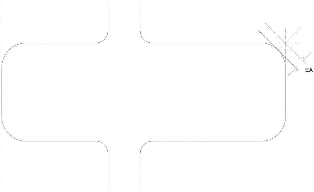
[0003] It has been found in practice that there will be many difficulties and problems in the processing of millimeter-wave radar PCBs using conventional PCB processes. For example, the SMT graphics on the millimeter-wave radar PCB cannot be realized on the basis of the conventional process. The included angle is a right angle, that is, the requirement that the EA value ≤ 10um; among them, the EA value refers to: the distance between the vertex of the ellipse after the actual processing of the angle between two adjacent sides of the SMT graphic and the intersection point of the theoretical adjacent two sides, such as figure 1 As shown, the distance is the EA value, and the usual design standard is that the EA value≤10um

Method used


Image

  • Method for manufacturing millimeter-wave radar PCB
  • Method for manufacturing millimeter-wave radar PCB
  • Method for manufacturing millimeter-wave radar PCB

Examples


Embodiment Construction

[0013] In order to enable those skilled in the art to better understand the solutions of the present invention, the following will clearly and completely describe the technical solutions in the embodiments of the present invention in conjunction with the drawings in the embodiments of the present invention. Obviously, the described embodiments are only It is an embodiment of a part of the present invention, but not all embodiments. Based on the embodiments of the present invention, all other embodiments obtained by persons of ordinary skill in the art without making creative efforts shall fall within the protection scope of the present invention.

[0014] The terms "first", "second", "third" and the like in the description and claims of the present invention and the above drawings are used to distinguish different objects, rather than to describe a specific order. Furthermore, the terms "include" and "have", as well as any variations thereof, are intended to cover a non-exclus...


PUM


Abstract

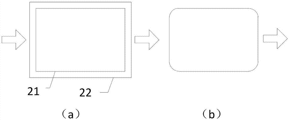
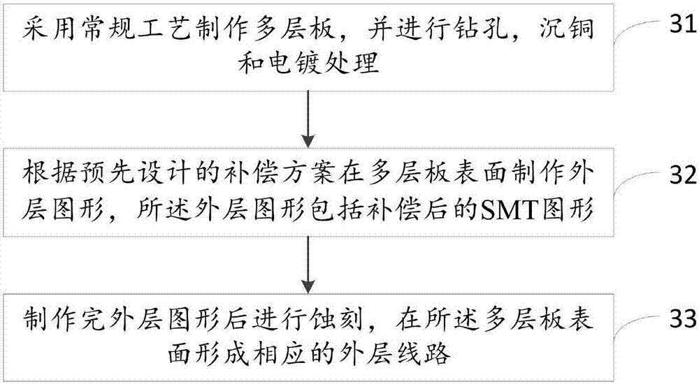
The invention discloses a method for manufacturing a millimeter-wave radar PCB. The method comprises the steps of manufacturing a multi-layer board by adopting a conventional process and carrying outdrilling, copper precipitation and electroplating treatment; manufacturing an outer pattern on the surface of the multi-layer board according to a pre-designed compensation scheme, wherein the outer pattern comprises a compensated SMT pattern; the compensated SMT pattern comprises an SMT body pattern, a conventional compensated pattern which surrounds the periphery of the SMT body pattern and is connected to the periphery of the SMT body pattern, and an additional compensated pattern located at the corner of the SMT body pattern; and the additional compensated pattern is a circular compensatedpattern; and etching after manufacturing the outer pattern and forming a corresponding outer circuit on the surface of the multi-layer board. According to the method disclosed by the embodiment of the invention, the outer pattern is designed and manufactured by adopting the special compensation scheme and the requirement that the EA value at the corner of the outer SMT pattern is smaller than orequal to 10mum can be met.

Description

technical field [0001] The invention relates to the technical field of PCBs, in particular to a method for manufacturing a millimeter-wave radar PCB. Background technique [0002] With the development of unmanned vehicles, the requirements for signal transmission frequency are getting higher and higher, and unmanned vehicles have made great progress. Unmanned driving has extremely high safety requirements. The millimeter-wave radar PCB (Printed Circuit Board, printed circuit board) is the hardware core of the millimeter-wave radar. In order to maintain sufficient signal strength of the radar antenna, the requirements for the millimeter-wave radar PCB are getting higher and higher. [0003] It has been found in practice that there will be many difficulties and problems in the processing of millimeter-wave radar PCBs by using conventional PCB processes. The included angle is a right angle, that is, the requirement that the EA value ≤ 10um; among them, the EA value refers to:...

Claims


Application Information

Patent Timeline
Patent Type & Authority Applications(China)
IPC IPC(8): H05K3/06H05K3/46
CPCH05K3/06H05K3/46H05K2201/0939
Inventor 郭长峰张学平陈冲周平剑崔荣缪桦
Owner SHENNAN CIRCUITS
Learn More