
Arterial embolectomy catheter

A catheter and bolt-knife technology, applied in the fields of medical science, surgery, surgical cutting instruments, etc., can solve the problems of inapplicability of CDT, prolonged hospitalization time, long time, etc., achieve rapid and continuous thrombectomy, eliminate guide wire and guide wire breakage the effect of risk

Active Publication Date: 2018-05-11
SHANGHAI BLUEVASCULAR MEDTECH CO LTD
View PDF7 Cites 11 Cited by
  • Summary
  • Abstract
  • Description
  • Claims
  • Application Information

AI Technical Summary

Problems solved by technology

However, the CDT treatment of DVT takes a long time for thrombolysis (the average thrombolysis time is 53.4 hours), which will lead to the following problems: long-term indwelling catheter, increasing the discomfort of the patient, and prolonging the hospital stay; repeated blood draws, requiring close monitoring and high-level care; Cases with severe swelling or even endangering the survival of the limbs are not conducive to opening the blood flow as soon as possible; the bleeding risk of thrombolytic drugs; CDT is not suitable for patients with high bleeding risk (such as severe hypertension, etc.), and is not suitable for patients in childbirth and pregnancy
The helical structure rotates very fast (40,000~60,000rpm) when the pump is pumped, which will drive the guide wire to rotate at a high speed, and some blood substances (such as fibrin, floating thrombus, etc.) will wrap around the guide wire exposed to the blood under the action of centrifugal force. On the surface of the wire, there is a risk of entangled thrombus, which may cause the guide wire to break

Method used


Image

  • Arterial embolectomy catheter
  • Arterial embolectomy catheter
  • Arterial embolectomy catheter

Examples


Embodiment Construction

[0035] The present invention will be further described below in conjunction with the accompanying drawings and embodiments. In the present invention, the distal end refers to the end away from the operator (such as a doctor); the proximal end refers to the end close to the operator (such as a doctor).

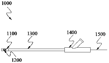
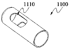
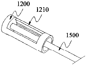
[0036] figure 1 It is a schematic diagram of the overall structure of the thrombectomy catheter in the embodiment of the present invention; figure 2 It is a schematic diagram of the structure of the plug head in the embodiment of the present invention; image 3 It is a schematic diagram of the connection structure between the bolt breaking knife and the transmission cable in the embodiment of the present invention; Figure 4 It is a schematic diagram of the structure of the partition tube with side wings in the embodiment of the present invention; Figure 5 It is a schematic cross-sectional view of the tail end connector in the embodiment of the present invention.

[0037]...


PUM


Abstract

The invention discloses an arterial embolectomy catheter which comprises an arterial embolectomy head, an embolism breaking knife, a transmission cable, a partition tube, an outer sheathing canal anda tail connecting piece, wherein the arterial embolectomy head is of a tubular hollow structure with at least one arterial embolectomy hole; the embolism breaking knife is of a tubular hollow structure with at least one blade point; the embolism breaking knife is installed inside the arterial embolectomy head; the embolism breaking knife is fixedly connected with the far end of the transmission cable; the near end of the arterial embolectomy head is fixedly connected with the far end of the outer sheathing canal; the near end of the outer sheathing canal is fixedly connected with the tail connecting piece; the partition tube is arranged outside the transmission cable in a sleeving manner; the near end of the partition tube is fixedly connected with the tail connecting piece; the embolism breaking knife is arranged outside the partition tube in a sleeving manner; a side hole is formed in the tail connecting piece; and the side hole is communicated with a cavity formed between the partition tube and the outer sheathing canal. According to the arterial embolectomy catheter provided by the invention, the partition tube is arranged outside the transmission cable, and the thrombus is prevented from winding with the transmission cable; and rapid and continuous arterial embolectomy is realized.

Description

technical field [0001] The invention relates to a medical catheter, in particular to a thrombectomy catheter. Background technique [0002] Deep venous thrombosis (DVT) of the lower extremities is a disease caused by abnormal coagulation of blood in the deep veins of the lower extremities. DVT leads to increased venous pressure, obstruction of blood return, swelling, pain, and dysfunction of the lower extremities, and the risk of thrombus dislodging. The dislodged thrombus travels with the blood flow to the pulmonary artery, which can cause pulmonary embolism (PE). If DVT is not effectively treated in the acute phase, thrombus organization, venous obstruction, loss of valve function, venous reflux, and venous hypertension will form post thrombosis syndrome (PTS), which endangers limb survival and life safety. [0003] By taking orally or injecting aspirin, heparin or warfarin, the drug can enter the blood system, effectively dissolve venous thrombosis, and greatly reduce th...

Claims


Application Information

Patent Timeline
Patent Type & Authority Applications(China)
IPC IPC(8): A61B17/3207A61B17/32A61B17/22
CPCA61B17/32002A61B17/320758A61B17/320783A61B2017/320024A61B2017/22079A61B2017/22038A61B2017/320775A61B2017/320032A61B2017/22039A61B2217/005
Inventor 韩建超张琳琳樊亚明刘梦钦史增佐朱清苗铮华
Owner SHANGHAI BLUEVASCULAR MEDTECH CO LTD
Learn More