Brake system and method for operating a brake system

A brake system and brake pedal technology, which is applied in the direction of brake control system, brake action activation device, brake, etc., can solve the problems of parking brake overload and damage, and achieve the effect of increasing the calculability

Active Publication Date: 2018-05-11
CONTINENTAL AUTOMOTIVE TECH GMBH
View PDF8 Cites 5 Cited by
  • Summary
  • Abstract
  • Description
  • Claims
  • Application Information

AI Technical Summary

Problems solved by technology

[0010] The disadvantage is that the parking brake is not designed for this application and can be overloaded and damaged as a result

Method used


Image

  • Brake system and method for operating a brake system
  • Brake system and method for operating a brake system
  • Brake system and method for operating a brake system

Examples


Embodiment Construction

[0034] Identical parts are provided with the same reference numerals in all figures.

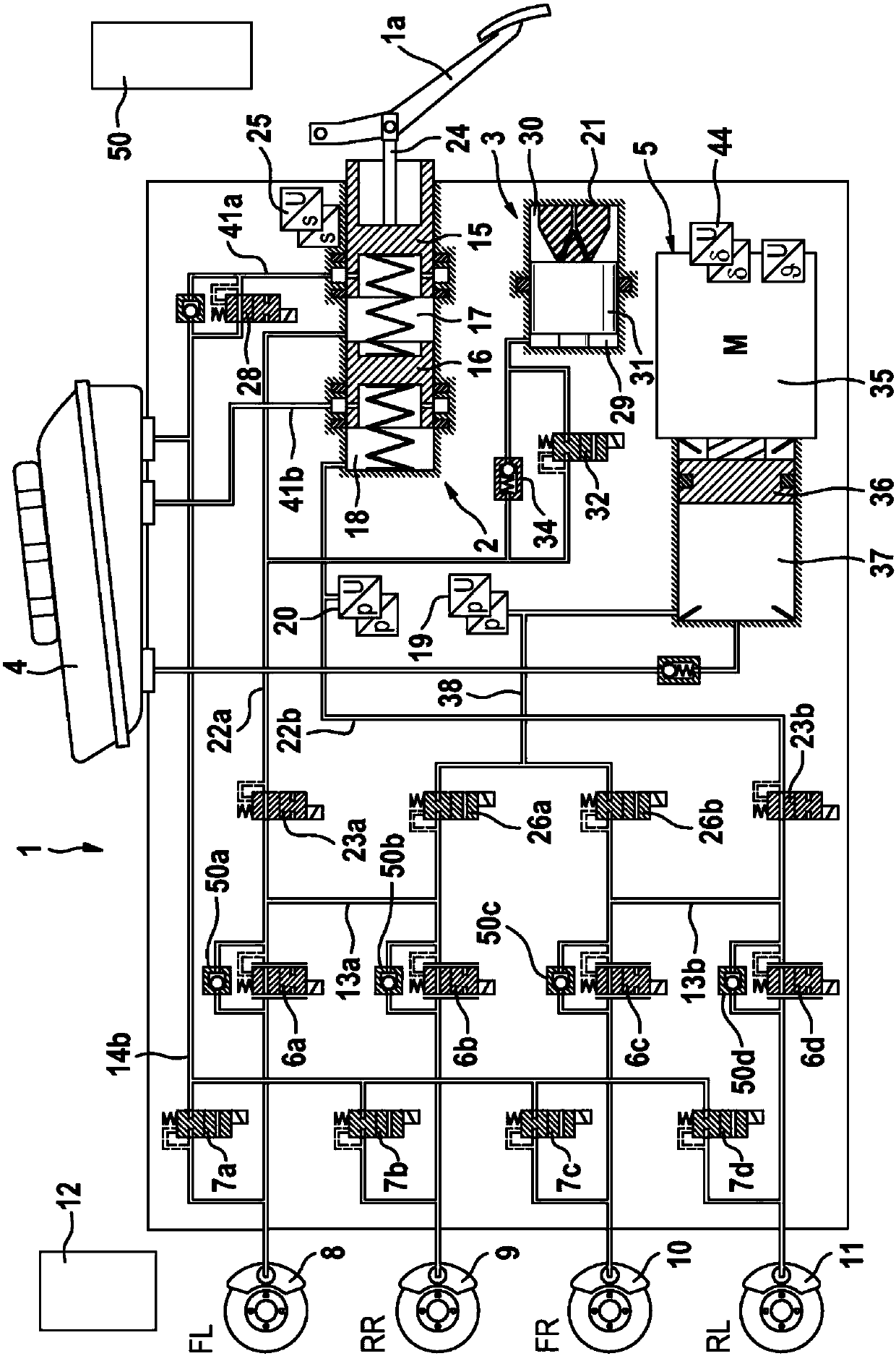
[0035] figure 1A preferred embodiment of the electrohydraulic brake system 1 or brake system according to the invention is shown in . The brake system 1 comprises a brake master cylinder 2 actuatable by means of an actuation or brake pedal 1 a, a simulation device 3 interacting with the brake master cylinder 2 , a pressure at atmospheric pressure assigned to the brake master cylinder 2 . Medium storage container 4, electrically controllable pressure supply device 5, electrically controllable pressure modulation device for adjusting the wheel-specific brake pressure and electronic control and regulation unit 12, said pressure supply device is equipped with hydraulic pressure The chamber 37 is constituted by a cylinder-piston assembly whose piston 36 is movable by an electromechanical actuator comprising an electric motor 35 and a rotation-translation transmission.

[0036] The pressure modu...


PUM


Abstract

The invention relates to an electro-hydraulic brake system (1) for a motor vehicle, comprising a main brake cylinder (2) which can be actuated by a brake pedal (1a) for actuating wheel brakes (8, 9, 10, 11), a pressure generating device (5) which can be activated electronically, an additional brake actuator (50) which can be activated electronically, an open and closed-loop control unit (12), wherein in a normal mode of operation the open and closed-loop control unit (12) detects a requirement for braking on the basis of the actuation of the brake pedal (1a) by the driver and activates the pressure generating device (5) to build up braking torque on the wheel brakes (8, 9, 10, 11), wherein, if the pressure generating device (5) is not activated or cannot be activated, the driver gains direct access to the wheel brakes (8, 9, 10, 11) and the open and closed-loop control unit (12) controls the additional brake actuator (50) to build up braking torque, wherein as a backup the open and closed-loop control unit (12) monitors the brake pedal travel and, when a predetermined pedal travel threshold value (120) is reached, activates the additional brake actuator to build up braking torque,and wherein, in the event of a succession of brake pedal actuations by the driver, the pedal travel threshold value (120) is increased at least once. The invention further relates to a method for operating an electro-hydraulic brake system.

Description

technical field [0001] The invention relates to an electrohydraulic braking system according to the preamble of claim 1 . The invention also relates to a method for operating an electrohydraulic brake system. Background technique [0002] In motor vehicle technology, "brake-by-wire" braking devices are becoming more and more popular. Such a brake system usually comprises, in addition to the brake master cylinder, which can be operated by the driver of the vehicle, an electrically ("by-wire") controllable pressure supply device, by means of which in the "brake-by-wire" operating mode to operate the wheel brakes. [0003] In such modern braking systems, in particular electrohydraulic braking systems with the "brake-by-wire" operating mode, the driver is decoupled from direct intervention on the brakes. When the pedal is actuated, the pedal decoupling unit and the simulator are frequently actuated, wherein the driver's desire to brake is detected by a sensor system. The ped...

Claims


Application Information

Patent Timeline
Patent Type & Authority Applications(China)
IPC IPC(8): B60T8/88B60T8/40
CPCB60T8/4081B60T8/885B60T2270/404B60T2270/82B60T7/042B60T13/741B60Y2400/81B60T8/17B60T13/588B60T13/66
Inventor M·尼佩尔特I·哈尔伯T·维肯赫费尔R·R·雷瓦尔K·伯格
Owner CONTINENTAL AUTOMOTIVE TECH GMBH
Why Eureka
Try Eureka