Method for manufacturing a cooling device for cooling a battery

A cooling device and battery technology, applied in secondary batteries, battery pack components, circuits, etc., can solve the problems of long process time, high manufacturing cost, unfavorable manufacturing process, etc., and achieve the effect of fast and flexible adaptation

Active Publication Date: 2021-04-20
ROBERT BOSCH GMBH
View PDF14 Cites 0 Cited by
  • Summary
  • Abstract
  • Description
  • Claims
  • Application Information

AI Technical Summary

Problems solved by technology

[0002] It has been found to be disadvantageous in the state of the art that cooling plates made of different components are joined
This leads to an energetically unfavorable production process and to relatively long process times
This is associated with high manufacturing costs

Method used


Image

  • Method for manufacturing a cooling device for cooling a battery
  • Method for manufacturing a cooling device for cooling a battery
  • Method for manufacturing a cooling device for cooling a battery

Examples


Embodiment Construction

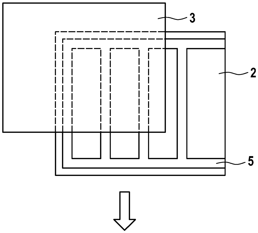
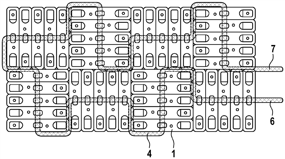
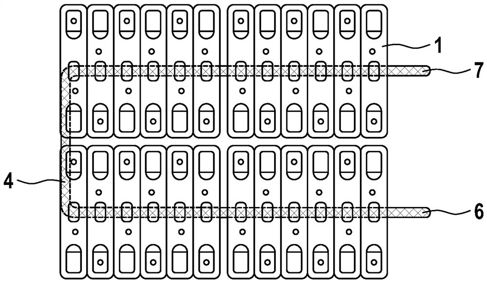
[0028] exist Figures 1 to 3 In the example shown, two sheets 2, 3 are extruded from thin butyl rubber. A means of insulating medium 5 is applied to the first plate 2 . Also, in detail, the not shown inlet zone 6 and outlet zone 7 can be coated (cf. image 3 ). Subsequently, as in figure 2 As shown in , the two plates 2, 3 are joined, for example by vulcanization at high pressure and temperature. Subsequently, as in image 3 As shown in , the corresponding intermediate regions, which are present between the arrangements of the cooling channels 4 , are removed, for example by stamping.

[0029] In this embodiment, it is possible in a development of the invention to introduce additional tissues or the like which improve the image 3 The shape and mechanical strength of the cooling channels are shown in the device.

[0030] is used to generate in figure 2 During the joining process of the device shown in it is possible to fill the means of the cooling channels, for exam...


PUM


Abstract

The invention relates to a method for producing a cooling device for cooling a battery (1), in particular for a battery (1) of a motor vehicle, in which two plates (2, 3) made of elastic material are designed to form one another The means of connected cooling channels (4) are joined to each other.

Description

Background technique [0001] High-voltage batteries, such as lithium batteries, are used as energy stores in electric or hybrid vehicles. Such lithium batteries (Li-ion batteries) are cooled or regulated by means of coolants. To this end, the battery or battery cell is in contact at its bottom and / or at the sides with a cooling plate that enables heat to be removed for cooling or heat to be supplied for heating. Such cooling plates are usually produced from metal, for example aluminum, and are designed with internal flow channels and inlet or outlet nipples. [0002] It has been found to be disadvantageous in the prior art to join cooling plates composed of different components. This leads to an energetically unfavorable production process and to relatively long process times. This is associated with high manufacturing costs. [0003] DE 20 2012 102 969 U1 discloses a battery cooling device in which a plurality of cooling tubes are prestressed against the battery for therma...

Claims


Application Information

Patent Timeline
Patent Type & Authority Patents(China)
IPC IPC(8): H01M10/625H01M10/6556H01M50/244B21D53/02F28F3/12F28F21/06H01M50/204H01M50/227
CPCH01M10/625H01M10/6556Y02E60/10H01M50/204H01M50/227
Inventor T.科勒闫小峰L.洛伦茨A.德尔C.勒夫
Owner ROBERT BOSCH GMBH
Why Eureka
Try Eureka