Dynamic decoupling method and system for accelerometer

A dynamic decoupling, accelerometer technology, applied in the testing/calibration of velocity/acceleration/shock measurement equipment, velocity/acceleration/shock measurement, measurement devices, etc., can solve the problem of large decoupling error, poor real-time performance, The coupled model is difficult to estimate accurately and other problems, to achieve the effect of reducing complexity, reducing computational burden, and good applicability

Inactive Publication Date: 2018-05-15
CHINA UNIV OF GEOSCIENCES (WUHAN)
View PDF9 Cites 4 Cited by
  • Summary
  • Abstract
  • Description
  • Claims
  • Application Information

AI Technical Summary

Problems solved by technology

Firstly, the static calibration matrix of the multi-dimensional sensor is established through the calibration experiment, and then the calibration matrix is ​​decoupled by the least square method. This method is the most widely used static decoupling method at present. The decoupled output is still distorted due to truncation and rounding errors during the solution
In the early days, someone proposed an invariant dynamic decoupling method. In the force sensor decoupling, decoupling methods such as P parallel, serial, V parallel, and serial were tried. The disadvantage is that when the sensor dimension increases, the decoupling The network is also more complex
Later, someone applied the P parallel invariant decoupling method to wind tunnel strain gauge balance and gyroscope attitude sensing. Due to the constant parameters of the decoupling link, there is always a theoretical error.
Fang J, Zheng S, and Han B. proposed a decoupling method for out-of-angle dominant compensation. In this paper, the relationship matrix at some frequencies of the sensor is used as a constant diagonal compensation matrix to decouple the entire frequency band, resulting in decoupling in other frequency bands. large error
Su X proposed a decoupling method that combines invariant decoupling with genetic algorithms. Its decoupling model is difficult to accurately estimate and the decoupling effect is not ideal.
The above methods have achieved different degrees of decoupling effects, but they are all based on the known transfer function of the sensor, and it is difficult to apply to the decoupling of the sensor with an unknown transfer function.
In recent years, researchers have proposed a decoupling method based on sensor input and output data and analyzing dynamic calibration data, such as Yu D, Meng Q, Wang J, etc. proposed a neural network decoupling method based on the left inverse system , Yu A L proposed the decoupling method of wavelet neural network, Wei X, Hu G, Wang Y, Ding J and Gao F used BP neural network and RBF neural network to decouple multi-dimensional wrist force / torque sensor, Zhang J, Guo K And Xu C proposed the support vector machine decoupling method, Li B, Peng C, Zheng F, etc. used the genetic algorithm in the decoupling of the three-dimensional electric field sensor. The above methods have their own characteristics and effectively expand the scope of application, but there are still some shortcomings , For example, the blind signal separation method only stays in the simulation signal decoupling stage, and has not yet passed the experimental verification; the process neural network algorithm has established 10 hidden layers in the processing of 96 sets of dynamic data, and after 1764 iterations, the maximum error is reduced. to 0.05%, but the decoupling operation time exceeds 10s, and the real-time performance is not good
Therefore, although the existing dynamic decoupling methods have high-precision decoupling effects for multi-dimensional sensors with unknown transfer functions, the decoupling efficiency is low, and the current research is based on personal computers (PCs). There is still a gap in practical application

Method used


Image

  • Dynamic decoupling method and system for accelerometer
  • Dynamic decoupling method and system for accelerometer
  • Dynamic decoupling method and system for accelerometer

Examples


Embodiment Construction

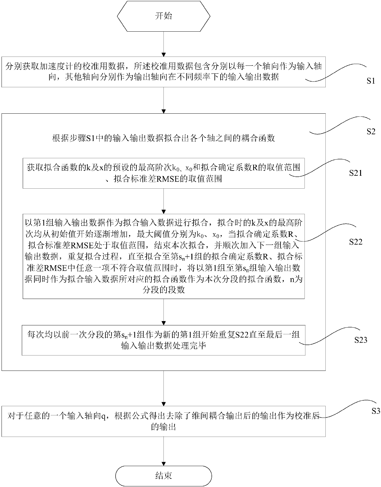
[0049] In order to have a clearer understanding of the technical features, purposes and effects of the present invention, the specific implementation manners of the present invention will now be described in detail with reference to the accompanying drawings. The applicable accelerometer of the present invention is a three-component MEMS accelerometer, or the acceleration contained in a three-axis acceleration sensor, a three-dimensional torque sensor, a six-dimensional torque sensor, a multi-dimensional wheel force sensor, a three-dimensional force flexible tactile sensor, and a three-component geophone One of them will be selected as an illustration below.

[0050] Taking the three-component MEMS accelerometer as an example, for a certain input axis a and the corresponding output axis that is only affected by it in theory, u i For the input i axis amplitude, y j is the output j-axis amplitude, when no coupling occurs, there is y a = u a , and after adding the inter-dimens...


PUM


Abstract

The invention discloses a dynamic decoupling method and system for an accelerometer. The method includes the following steps that: the calibration-used data of the accelerometer are acquired, whereinthe calibration-used data contain input and output data at different frequencies under a condition that each axis is adopted as an input axis, and the other axes are respectively taken as output axes;a coupling function between the axes is fitted according to the input and output data; and a calibrated output result is finally obtained according to the coupling function. According to the method of the present invention, the coupling function is processed in a segmented manner, so that the order of the coupling function can be lowered, and therefore, the complexity of decoupling can be decreased, and the amount of calculation is lower; and the calibration data are adopted as the input data of a dynamic fitting formula, which enables high applicability; solving operation that needs large computation amount only lies in the obtaining of constant coefficients in the coupling formula, and in actual decoupling, only the formula needs to be directly invoked, and therefore, the computation burden of a processor can be effectively reduced.

Description

technical field [0001] The present invention relates to the field of accelerometers, and more specifically, to a dynamic decoupling method and system for accelerometers. Background technique [0002] Due to the influence of factors such as placement structure, process, and integration of multiple sensitive components, multi-component accelerometers have the problem of inter-dimensional coupling in actual use. The phenomenon of inter-dimensional coupling refers to a certain non-electrical physical quantity in a single direction. When functioning, the output signal should only be generated in the corresponding axial direction, and the phenomenon that the output signal is also generated in the conversion channel not in this axial direction. [0003] The inter-dimensional coupling is incompletely linear. In some sensors, it is a single-increase / single-decrease nonlinearity, while some special sensors are multi-peak nonlinearity. The inter-dimensional coupling makes the multiple ...

Claims


Application Information

Patent Timeline
Patent Type & Authority Applications(China)
IPC IPC(8): G01P21/00
CPCG01P21/00
Inventor 宋俊磊杨至恒黄燕霞刘奇
Owner CHINA UNIV OF GEOSCIENCES (WUHAN)
Why Eureka
Try Eureka