Single-optical-fiber scanning device

A single optical fiber and device technology, which is applied in the field of imaging optical fiber devices and scanning, can solve the problems of difficult size, size limitation of controllable vibration devices, and difficult assembly process, etc.

Pending Publication Date: 2018-05-15
CHINA JILIANG UNIV
View PDF0 Cites 5 Cited by
  • Summary
  • Abstract
  • Description
  • Claims
  • Application Information

AI Technical Summary

Problems solved by technology

On the one hand, the assembly process of such millimeter-sized devices is difficult. On the other hand, the optical fiber scanning system based on this assembly process is limited by the size of the controllable vibration device, and it is difficult to achieve a size comparable to that of optical fibers.

Method used


Image

  • Single-optical-fiber scanning device
  • Single-optical-fiber scanning device

Examples


Embodiment Construction

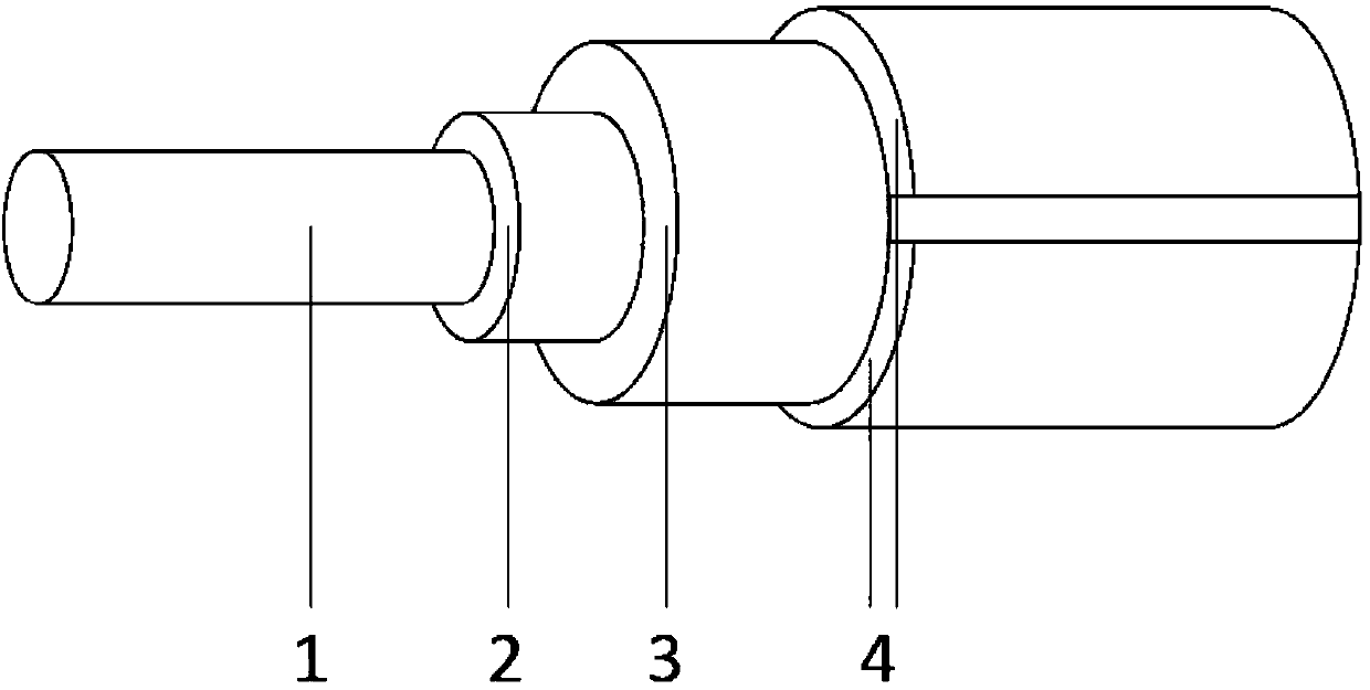
[0016] Attached below figure 2 A vibratable optical fiber described in the present invention and its usage are further described in detail.

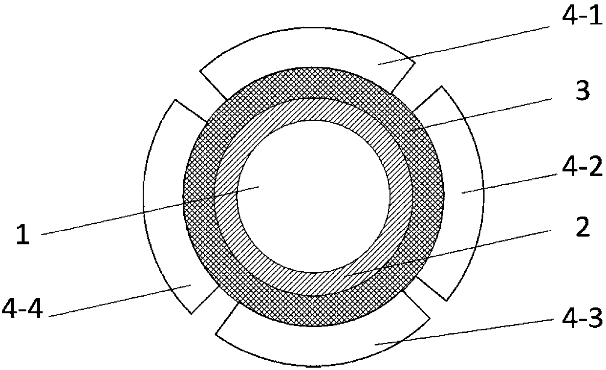
[0017] A kind of vibrating optical fiber, the specific structure is as follows: the optical fiber 1 based on the glass core is used as the output end of the scanning light, the outer layer of the optical fiber 1 is wrapped with a layer of gold electrode 2, and lead zirconate titanate is prepared on the gold electrode 2 For the film 3, 4 equal parts of gold electrodes 4-1, 4-2, 4-3, 4-4 are also prepared on the lead zirconate titanate film 3. The gold electrode 2 , the lead zirconate titanate film 3 and the gold electrode 4 form a structure similar to a sandwich, and the gold electrode 4 is insulated from the gold electrode 2 .

[0018] During operation, 20V sinusoidal voltage and -20V sinusoidal voltage are respectively applied to electrodes 4-1 and 4-3, and opposite electrodes 4-2 and 4-4 are respectively vacant, and gold electrode 2 ...


PUM


Abstract

The invention relates to a single-optical-fiber scanning device, which consists of an optical conduction fiber core 1, an external metal coating layer 2, a piezoelectric thin layer 3 and a metal electrode layer 4, wherein the device integrates a piezoelectric vibration control system based on the piezoelectric thin layer 3 onto the optical conduction fiber core 1; by loading required electric signals to the external metal coating layer 2 and the metal electrode layer 4, the periodic deformation of the piezoelectric thin layer 3 can be caused, so that the optical fiber vibration can be realized. Through the integration, the single-optical-fiber scanning function can be realized; the dimension of a core element of the vibration scanning system can be effectively reduced; the application to afine micro nanometer scanning system can be facilitated.

Description

technical field [0001] A single optical fiber scanning device belongs to the field of optical fibers, in particular to an optical fiber device that can be used for scanning and imaging. Background technique [0002] Optical fiber is an important optical waveguide device. Using optical fiber to guide the light emitted by the light source or collecting image information at the end of the optical fiber is two important aspects of optical fiber applications, such as medical endoscope systems and laser projection systems. Usually the complete fiber core diameter ranges from tens of microns to hundreds of microns. In order to form a light source exit surface or image collection end with a certain size, the form of fiber bundles is mostly used to expand the area of ​​the fiber end face, thereby increasing the information collection surface. This optical fiber application method is difficult to fully utilize the advantages of the optical fiber, not only the formed end faces are limi...

Claims


Application Information

Patent Timeline
IPC IPC(8): G02B26/10
CPCG02B26/103
Inventor 孟彦龙王玲莉金国君檀珺
Owner CHINA JILIANG UNIV
Why Eureka
Try Eureka