Anti-battery virtual current circuit in artificial intelligence electric vehicle battery charging
An artificial intelligence electric vehicle and battery charging technology, which is applied in battery circuit devices, battery/fuel cell control devices, electric vehicles, etc., can solve problems such as phantom power and battery ohmic polarization, and achieve moderate charging time and reduce battery life. Effects of ohmic polarization and elimination of virtual electricity
- Summary
- Abstract
- Description
- Claims
- Application Information
AI Technical Summary
Problems solved by technology
Method used
Image
Examples
Embodiment 1
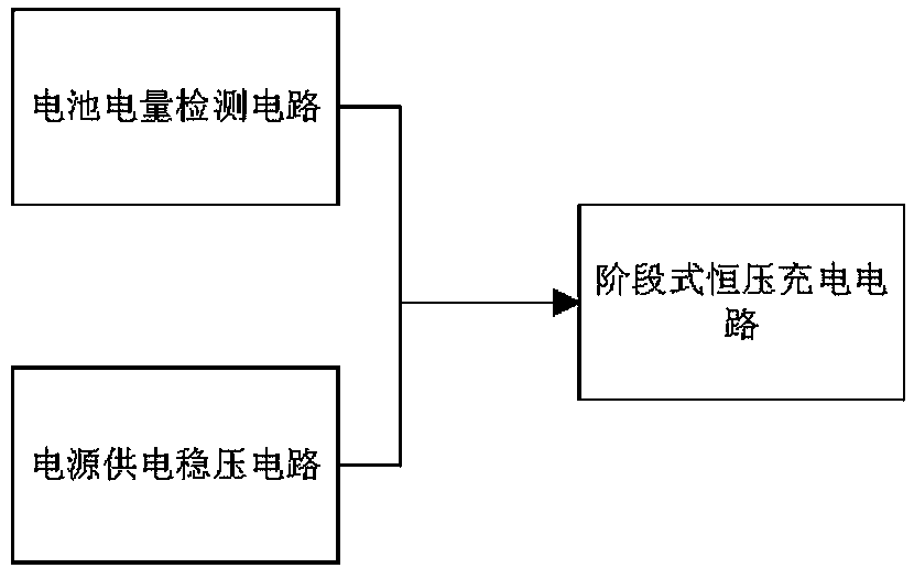
[0014] The first embodiment, the anti-battery virtual power circuit during artificial intelligence electric vehicle battery charging, includes a battery power detection circuit, a power supply voltage stabilizing circuit, and a staged constant voltage charging circuit. The battery power detection circuit reads the model number through the USB interface J1. HDGC3912 intelligent battery internal resistance tester tests the positive and negative potentials of the battery when charging the artificial intelligence electric vehicle battery. The output signal of the battery power detection circuit is the three-stage voltage regulation control signal of the stage-type constant voltage charging circuit. The control stage is constant The voltage charging circuit receives the input of the power supply voltage regulator circuit to charge the artificial intelligence electric vehicle battery in stages;
[0015] The staged constant voltage charging circuit is divided into three stages of chargin...
Embodiment 2
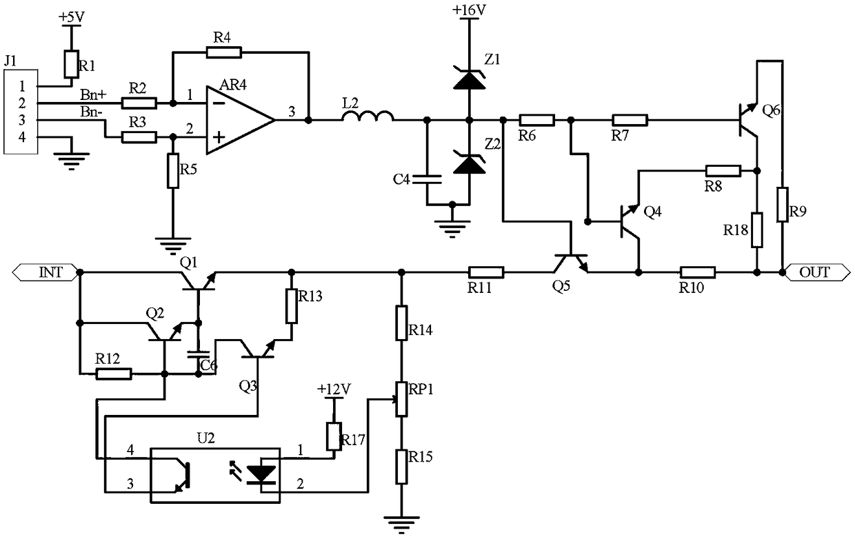
[0016] Second embodiment, on the basis of the first embodiment, the battery power detection circuit reads the positive electrode potential Bn+ and negative electrode of the battery when charging the artificial intelligence electric vehicle battery tested by the HDGC3912 smart battery internal resistance tester through the USB interface J1 The potential Bn- is calculated by the subtraction circuit with the operational amplifier AR4 as the core, and the LC filter circuit composed of the inductance L2 and the capacitor C4 is filtered, and the series-connected Zener tubes Z1 and Z2 are stabilized and output the voltage corresponding to the battery power. USB interface J1 The pin 1 of the power supply terminal is connected to the power supply +5V through the resistor R1, the pin 4 of the USB interface J1 is the ground terminal, and the pins 2 and 3 of the USB interface J1 are the data terminals. The read positive potential Bn+ and The negative potential Bn- is connected to the invert...
PUM
 Abstract
Description
Claims
Application Information
 - R&D
- Intellectual Property
- Life Sciences
- Materials
- Tech Scout
- Unparalleled Data Quality
- Higher Quality Content
- 60% Fewer Hallucinations
Browse by: Latest US Patents, China's latest patents, Technical Efficacy Thesaurus, Application Domain, Technology Topic, Popular Technical Reports.
© 2025 PatSnap. All rights reserved.Legal|Privacy policy|Modern Slavery Act Transparency Statement|Sitemap|About US| Contact US: help@patsnap.com


