Circular lifting type solar energy charging pile

A solar energy, lift-type technology, applied in current collectors, electric vehicles, electrical components, etc., can solve problems such as simple structure, and achieve the effects of convenient locking and unlocking operations, stable and precise connection and coordination, and simple overall structure.

Active Publication Date: 2018-05-15
湖南智行壹站信息科技有限公司
View PDF3 Cites 6 Cited by
  • Summary
  • Abstract
  • Description
  • Claims
  • Application Information

AI Technical Summary

Problems solved by technology

At present, most of the solar charging piles for electric vehicles are simple in structure, and the electric vehicles are charged by taking power from the grid, and the solar charging piles are exposed outdoors, without wind and rain protection measures

Method used


Image

  • Circular lifting type solar energy charging pile
  • Circular lifting type solar energy charging pile
  • Circular lifting type solar energy charging pile

Examples


Embodiment 1

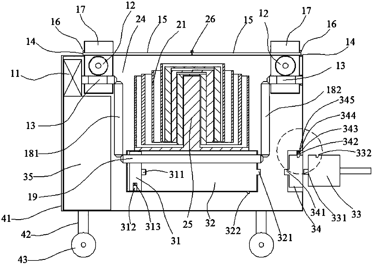
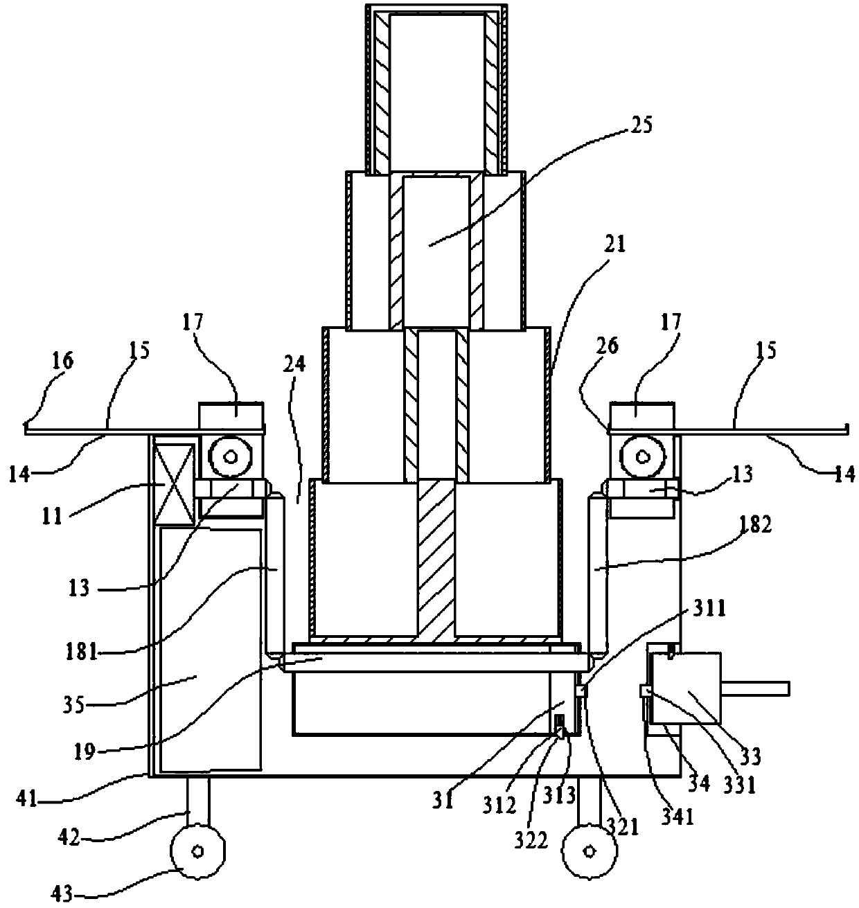
[0033] Such as Figure 1-4 As mentioned above, this embodiment provides a circular lifting solar charging pile, which includes a transmission system 1 located inside the housing 41, a solar panel lifting system 2 and an electric power system 3; the transmission system 1 includes two symmetrical worms 13. One end of the left worm 13 is driven and connected to the motor 11, and the other end is connected to the upper end of the vertical linkage rod 181 through the bevel gear drive, and the lower end of the linkage rod 181 is connected to the left end of the horizontal screw rod 19 through the bevel gear drive, and the right end of the screw rod 19 passes through the cone The tooth drive is connected to the lower end of the linkage rod 182, and the upper end of the linkage rod 182 is connected to the right worm 13 through a bevel gear drive; The plate 21 stretches out with the rise of the hydraulic cylinder 25 and is distributed in steps. The lower end of the outer circumference ...

Embodiment 2

[0035] Such as Figure 1-4As mentioned above, this embodiment provides a circular lifting solar charging pile, which includes a transmission system 1 located inside the housing 41, a solar panel lifting system 2 and an electric power system 3; the transmission system 1 includes two symmetrical worms 13. One end of the left worm 13 is driven and connected to the motor 11, and the other end is connected to the upper end of the vertical linkage rod 181 through the bevel gear drive, and the lower end of the linkage rod 181 is connected to the left end of the horizontal screw rod 19 through the bevel gear drive, and the right end of the screw rod 19 passes through the cone The tooth drive is connected to the lower end of the linkage rod 182, and the upper end of the linkage rod 182 is connected to the right worm 13 through a bevel gear drive. The top of the worm 13 is driven to connect to the worm gear 12, and the top of the worm gear 12 is driven to connect to the rack 14 in the ho...

Embodiment 3

[0037] Such as Figure 1-4 As mentioned above, this embodiment provides a circular lifting solar charging pile, which includes a transmission system 1 located inside the housing 41, a solar panel lifting system 2 and an electric power system 3; the transmission system 1 includes two symmetrical worms 13. One end of the left worm 13 is driven and connected to the motor 11, and the other end is connected to the upper end of the vertical linkage rod 181 through the bevel gear drive, and the lower end of the linkage rod 181 is connected to the left end of the horizontal screw rod 19 through the bevel gear drive, and the right end of the screw rod 19 passes through the cone The lower end of the linkage rod 182 is connected to the tooth drive, and the upper end of the linkage rod 182 is connected to the right worm 13 through a bevel gear drive. , two protective plates 15 are combined to cover the cavity 24, the left and right ends of the protective plate 15 are provided with baffles...


PUM


Abstract

The invention provides a circular lifting type solar energy charging pile, which comprises a driving system, a solar energy panel lifting system and a power system located in a shell. The solar energypanel lifting system comprises multiple circular solar energy panels held in a holding cavity and sequentially nested on the outer side of a hydraulic air cylinder; the circular solar energy panels stretch out along with the rising of the hydraulic air cylinder and are distributed step by step; an outer clamping ring or at least two clamping blocks arranged at an interval are arranged on the lower end of an outer circumference of the circular solar energy panel on the inner side, a corresponding inner clamping ring or at least two clamping blocks arranged at an interval are arranged on the upper end of an inner circumference of the adjacent circular solar panel on the outer side, so that the circular solar energy panels are not separated when stretching out; the power system comprise a power supply tank and an energy storage battery connected electrically. According to the circular lifting type solar energy charging pile provided by the invention, the circular solar energy panels canbe automatically stretched, and all direct or indirect sunlight in an ambient environment is fully utilized, so that the circular lifting type solar energy charging pile is higher in efficiency, energy saving, environmentally friendly, and safe and stable during a charging process.

Description

technical field [0001] The invention relates to a circular lifting solar charging pile. Background technique [0002] With the increasingly intensified contradictions between economic development, energy supply, and environmental pollution, energy conservation and consumption reduction and reduction of dependence on fossil fuels have become urgent problems to be solved for the sustainable economic development of countries all over the world. Electric vehicles have the advantages of fuel saving, environmental protection, and high efficiency. Scientists and industrial circles all over the world generally believe that electric vehicles are an important clean transportation tool in the 21st century. The charging system provides energy supply for the operation of electric vehicles. It is an important basic support system for electric vehicles and an important link in the process of commercialization and industrialization of electric vehicles. [0003] In the charging system, sol...

Claims


Application Information

Patent Timeline
Patent Type & Authority Applications(China)
IPC IPC(8): H02J7/35
CPCH02J7/35
Inventor 李梅
Owner 湖南智行壹站信息科技有限公司
Why Eureka
Try Eureka