Switched reluctance generator power converter and regulation method

A technology of generator power and switched reluctance, which is applied to control the direction of the generator through the change of the magnetic field, can solve the problems that the excitation power supply voltage cannot be adjusted independently, increase the complexity of the system structure, and the excitation power supply cannot work, etc., to achieve stability, Simple structure, improved fault tolerance and reliability

Active Publication Date: 2018-05-15
CHINA JILIANG UNIV
View PDF4 Cites 12 Cited by
  • Summary
  • Abstract
  • Description
  • Claims
  • Application Information

AI Technical Summary

Problems solved by technology

[0005] The main circuit of the power converter is currently dominated by an asymmetrical half-bridge structure, and many devices are used; whether it is a self-excited or separately-excited power converter, the excitation power supply voltage cannot be adjusted independently, although there are currently some excitation voltage and power generation The voltage (switched reluctance generator output voltage) is decoupled and independently adjustable circuit, but it is lacking in reliability. After the excitation power switch tube fails, the excitation power supply often cannot work, that is, the entire switched reluctance generator Machine system must stop working
[0006] After the generator generates electric energy, it often needs to output and then increase the voltage level to facilitate grid connection or high-voltage load requirements. In the field of switched reluctance generator systems, most of the time, step-up measures are added after generating output, such as inverter first. Then it is boosted by a step-up transformer, or the output DC is realized by a DC step-up circuit, etc., which increases the structural complexity of the entire system.
[0007] The torque ripple problem of switched reluctance motors has always been a heart problem in the industry. The torque ripple of switched reluctance generators also often brings about the problem of low power quality. Some excitation power supplies in the industry, especially self-excited structures Yes, the voltage and current output by the excitation power supply often have large periodic fluctuations, which will inevitably increase the torque ripple problem

Method used


Image

  • Switched reluctance generator power converter and regulation method

Examples


Embodiment Construction

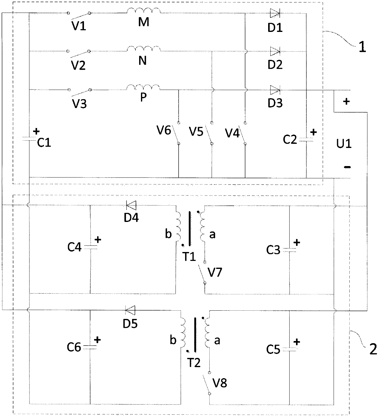
[0023] The switched reluctance generator power converter of this embodiment is composed of a main circuit 1 and an excitation circuit 2. The main circuit 1 outputs electric energy, and its output ends are connected to the input ends of the excitation circuit 2, and the output ends of the excitation circuit 2 Connect the two ends of the input of the main circuit 1; the switched reluctance generator has a three-phase winding structure.

[0024] The main circuit consists of a first capacitor C1, a second capacitor C2, a first switch V1, a second switch V2, a third switch V3, a fourth switch V4, a fifth switch V5, a sixth switch V6, a A winding M, a second winding N, a third winding P, a first diode D1, a second diode D2, and a third diode D3, and the anode of the first capacitor C1 is used as the input anode of the main circuit 1 and connected The anode of the first switch tube V1, the anode of the second switch tube V2, and the anode of the third switch tube V3, the cathode of t...


PUM


Abstract

Provided are a switched reluctance generator power converter and a regulation method. The power converter includes a main circuit and an excitation circuit, the control loop of each phase winding of the main circuit is composed of two switch tubes and a diode, the two switch tubes are closed when in the excitation process, and the switch tube at the lower end is disconnected during the generation,the switch tube at the upper end and the diode generate power in a flow current manner, the power generation voltage is output to obtain a large gain; the excitation circuit is of a structure and a mode that two isolation type voltage transformation circuits work alternatively after the two isolation type voltage transformation circuits are connected in parallel, in addition to the decoupling ofthe adjustable output excitation voltage from the generation voltage, the two switch tubes are switched on and off alternately, the current output after parallel connection is more stable and the torque ripple inhibition is facilitated, and the whole system is more suitable for being used by a power generation terminal of a local-area direct-current microgrid with medium and small power.

Description

technical field [0001] The invention relates to the field of switched reluctance motor systems, in particular to a switched reluctance generator power converter system with an alternately working excitation circuit decoupled from excitation voltage and a direct high-gain main circuit of generating voltage and a control method thereof. Background technique [0002] The switched reluctance motor has a simple and solid structure, low manufacturing cost, no windings on the rotor, no permanent magnets, high reliability, and broad application prospects. As a generator, it has the ability to perform high performance in a wide speed range. [0003] Switched reluctance generators generally have 2-5 phase windings placed on the stator, and the phase windings that are energized are determined according to the relative position of the salient poles between the stator and rotor. The operation of each phase winding is generally divided into two stages: excitation and power generation. The ...

Claims


Application Information

Patent Timeline
Patent Type & Authority Applications(China)
IPC IPC(8): H02P9/30
Inventor 孙冠群
Owner CHINA JILIANG UNIV
Why Eureka
Try Eureka