
Laser welding head with coaxial light path

A technology of laser welding head and coaxial light, which is applied in laser welding equipment, welding equipment, metal processing equipment, etc., can solve the problems that the size of the spot at the laser focus cannot be changed, and the laser welding equipment is affected by the structure of the welded product, etc. The size can be adjusted to solve the effect of easy interference and strong reliability

Pending Publication Date: 2018-05-18
SHENZHEN HYMSON LASER INTELLIGENT EQUIP CO LTD
View PDF6 Cites 15 Cited by
  • Summary
  • Abstract
  • Description
  • Claims
  • Application Information

AI Technical Summary

Problems solved by technology

[0006] In order to solve the above-mentioned problems in the prior art, the present invention provides a laser welding head with a coaxial optical path to solve the problem that the temperature control process of the existing laser welding equipment is easily affected by the structure of the welding equipment and the structure of the welded product, and The problem that the spot size at the laser focus cannot be changed

Method used

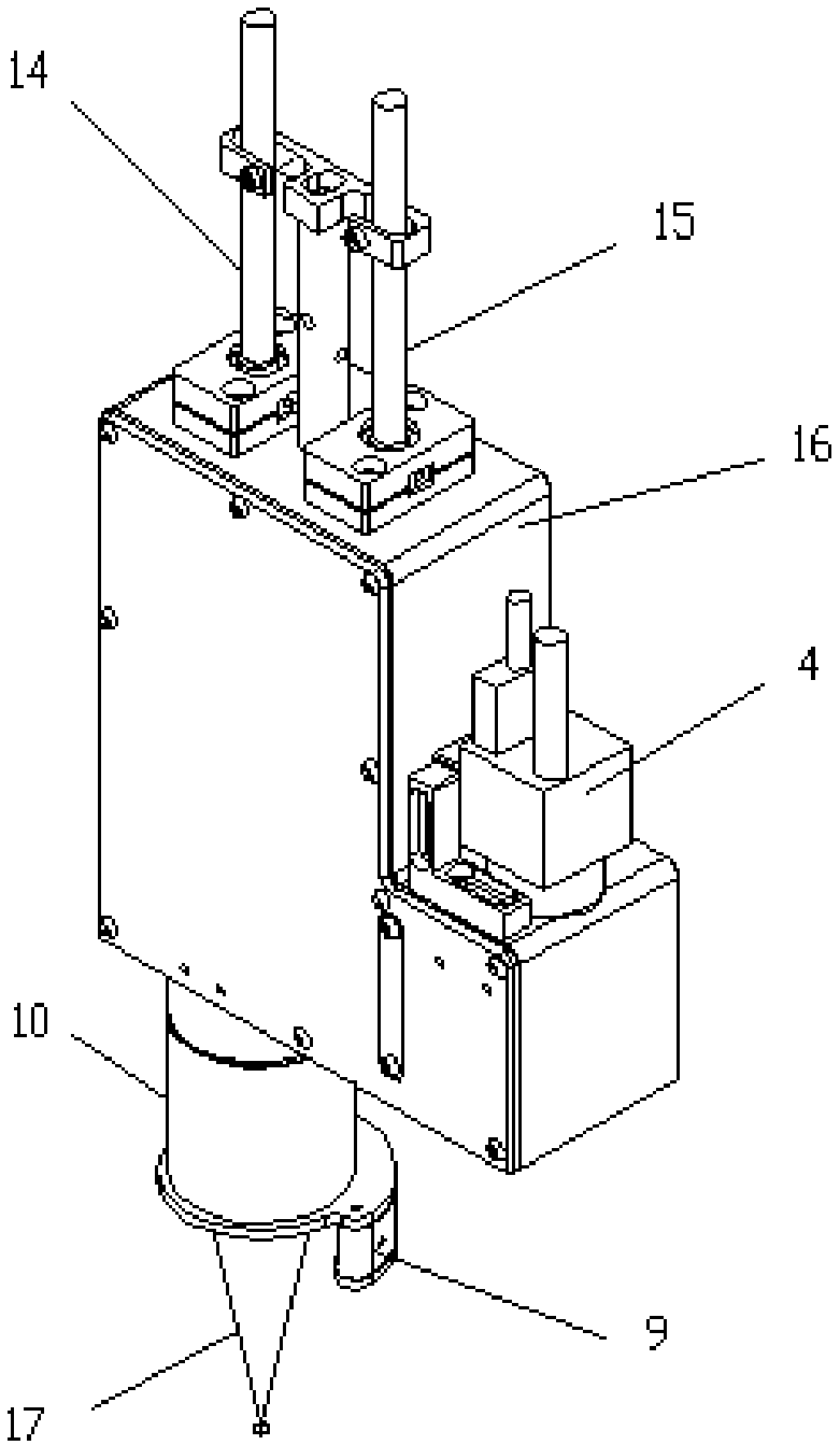

Image

  • Laser welding head with coaxial light path
  • Laser welding head with coaxial light path
  • Laser welding head with coaxial light path

Examples


Embodiment Construction

[0024] The present invention will be further described below in conjunction with the accompanying drawings and specific embodiments. Terms such as "upper", "lower", "left", "right", "middle" and "one" quoted in the preferred embodiment are only for convenience of description, and are not used to limit the scope of the present invention. The scope of implementation and the change or adjustment of its relative relationship shall also be regarded as the scope of implementation of the present invention without substantive changes in technical content.

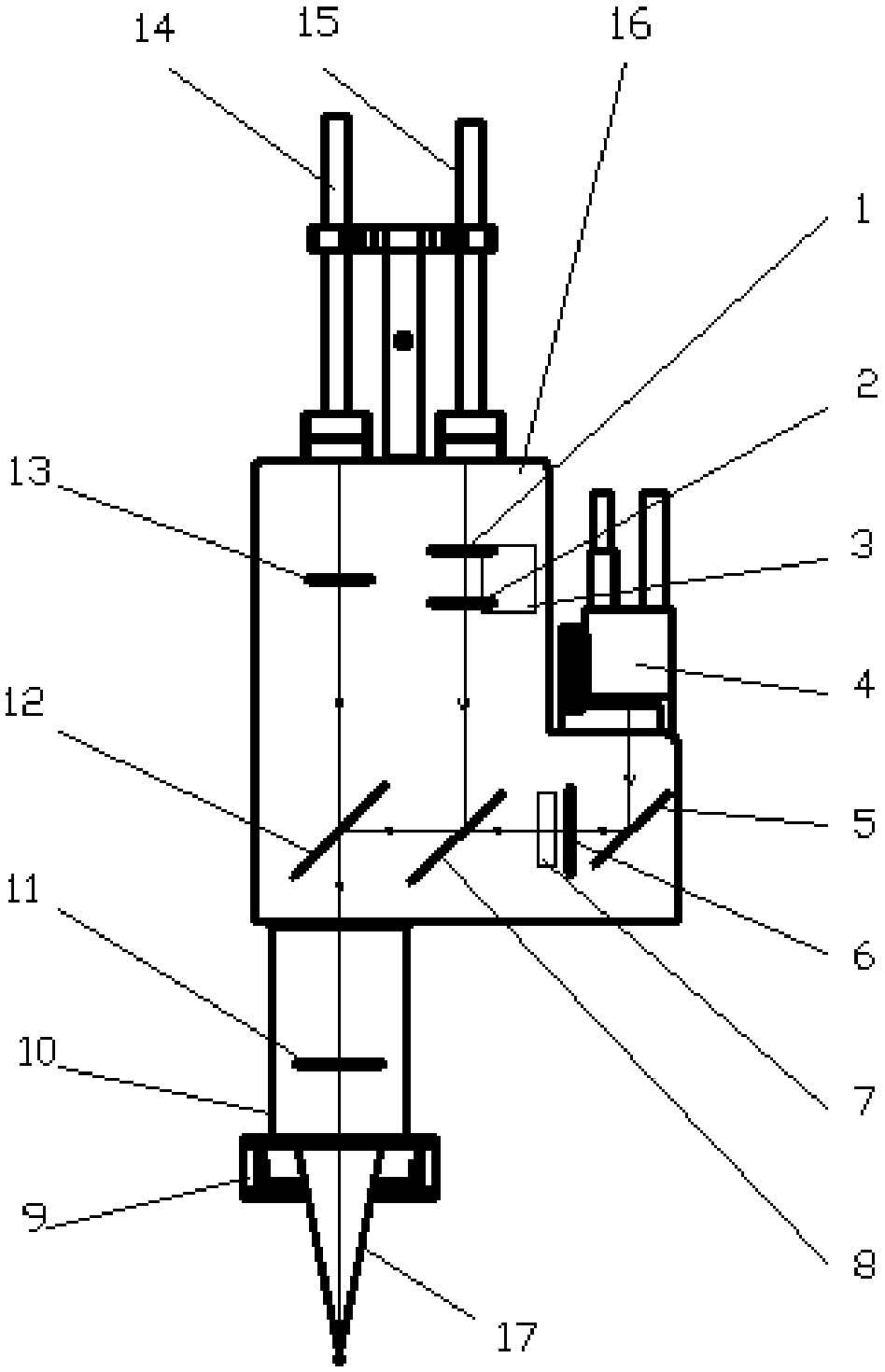
[0025] The laser welding head of the coaxial optical path of the present invention is connected to the laser welding welding system, and is used to provide and control the laser optical fiber 15, the infrared temperature measuring beam and the visual positioning and monitoring beam during the welding process, so as to realize precise welding control .

[0026] figure 2 A structural schematic diagram of an example provided for th...


PUM


Abstract

The invention discloses a laser welding head with a coaxial light path. The laser welding head comprises a light path cavity, a laser emitting head, a laser optical fiber used for providing laser beams, an infrared temperature measuring optical fiber used for collecting infrared temperature measuring light beams and a camera used for providing visual positioning and monitoring light beams, whereinthe laser optical fiber, the infrared temperature measuring optical fiber and the camera are correspondingly connected to the light path cavity; the light path cavity combines the laser beams, the infrared temperature measuring light beams and the visual positioning and monitoring light beams into a three-in-one coaxial light beam, and the coaxial light beam passes through the laser emitting headso as to perform laser welding, temperature measuring and visual positioning on the position of a welding spot located at the laser emitting head; and the laser emitting head is internally provided with a laser focusing lens used for transmitting the three-in-one coaxial light beam and focusing the laser beams. According to the laser welding head, the coaxial light beam makes temperature controland vision positioning play effective roles at the special welding spot position, the control is accurate, the reliability is higher, therefore, the problem that the temperature control detection canbe easily interfered is solved; and moreover, the size of the light spot at the focal point of the laser can be adjusted so as to be suitable for bonding pads with different sizes.

Description

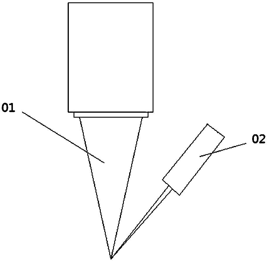
technical field [0001] The invention relates to the field of laser welding equipment, in particular to a laser welding head with a coaxial optical path. Background technique [0002] Laser soldering uses high-energy laser pulses to locally heat the material in a small area. The energy of the laser radiation is absorbed by the material and then heated up to form a specific molten pool after melting the material. There are roughly two structures of solder that are widely used at present: one is the traditional electric soldering iron automatic welding; the other is the laser welding structure. [0003] The traditional electric soldering iron welding is a contact welding process that cannot meet the welding of tiny precision devices, and cannot meet the precise positioning. [0004] The existing laser welding can basically satisfy the welding of tiny precision devices, such as figure 1 As shown, it is a structural schematic diagram of the laser welding head of the existing la...

Claims


Application Information

Patent Timeline
Patent Type & Authority Applications(China)
IPC IPC(8): B23K26/03B23K26/064B23K26/21B23K26/70
CPCB23K26/032B23K26/064B23K26/21B23K26/702
Inventor 赵盛宇刘明清唐铁锤周宇超林国栋田亮张松岭宋玉立
Owner SHENZHEN HYMSON LASER INTELLIGENT EQUIP CO LTD
Learn More