Preparation method of flow-state concrete laminated slab

A technology of fluid concrete and laminated slabs, which is applied in the manufacture of tools, ceramic molding workshops, ceramic molding machines, etc., can solve the problems of increased concrete costs, increased labor intensity and workload, and low molding efficiency, achieving uniform, stable and reliable strength , Reduce dusty, beautiful surface quality

Inactive Publication Date: 2018-05-18
重庆恒昇大业建筑科技集团有限公司
View PDF6 Cites 2 Cited by
  • Summary
  • Abstract
  • Description
  • Claims
  • Application Information

AI Technical Summary

Problems solved by technology

[0003] First, since the plasticity of dry hard concrete is not as strong as that of fluid concrete, strong vibration force is needed to improve the compactness of the molding, which leads to low molding efficiency;
[0004] Second, due to insufficient compactness or even unevenness, many local strengths of components are weak, so there is a certain risk in the use of components. This risk is generally avoided by increasing the strength level, resulting in an increase in the cost of concrete;
[0005] Third, since the dry and rigid laminated boards are all made of extrusion molding technology, it is normal for the appearance quality to appear honeycomb and pockmarked, and the bottom of the board needs to be repaired twice, which increases the labor intensity and workload;
[0006] Fourth, since the extrusion molding process is used for dry and rigid laminated boards, a single-layer production method must be adopted, which requires a large number of working surfaces and ground molds to meet the production quantity, and the workshop occupies a large area;
[0007] Fifth, plastic concrete adopts a single-piece production molding process, which requires a large number of molds, cumbersome procedures, and low production efficiency. It also requires a large number of working surfaces and ground molds to meet the production quantity, and the plant occupies a large area

Method used


Image

  • Preparation method of flow-state concrete laminated slab
  • Preparation method of flow-state concrete laminated slab
  • Preparation method of flow-state concrete laminated slab

Examples


Embodiment Construction

[0038] Below in conjunction with accompanying drawing and embodiment the present invention will be further described:

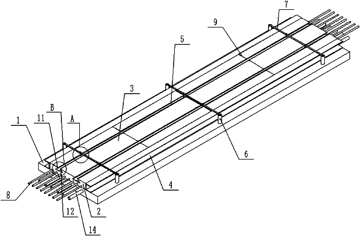
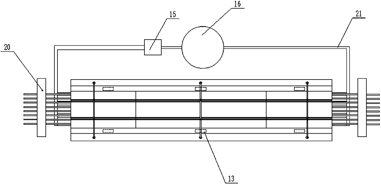
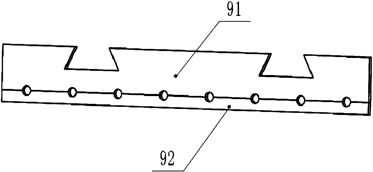
[0039] see Figure 1 to Figure 5 As shown, the invention discloses a method for preparing a fluidized concrete composite slab, comprising the following steps:

[0040] (1) Clean the ground form with the baffle plate 2 at both ends, the setting of the baffle plate 2 makes the concrete not overflow from the two ends of the ground form 1, and the ground form 1 adopts the long-line platform ground form 1, and the long-line platform ground form 1 The length is generally 100-150m, that is to say, after one-time casting, the laminated plate can be cut into multiple single laminated plates 3 as required, and the side mold 4 and rib mold 5 are prepared. The setting of the side mold 4 makes Concrete will not overflow from the side of the ground form 1. Since the laminated slab needs to reserve a notch for secondary pouring of concrete in the later process (such as bui...


PUM


Abstract

The invention discloses a preparation method of a flow-state concrete laminated slab. The preparation method comprises the following steps of 1, cleaning a floor mold, wherein the two ends of the floor mold are provided with baffles; 2, coating the floor mold, rib molds, the baffles and the inner side face of a side mold with an isolating agent through brushing, or arranging isolating molds in a covering manner; 3, arranging a rebar set at each of the two ends of the floor mold through a prestressed anchorage device; 4, connecting rebar protective layer cushion blocks or pre-buried parts to the rebars; 5, fixing multiple partition plates to the rebars at intervals according to the length of the laminated slab needing to be obtained; 6, producing flow-state concrete, and pouring the flow-state concrete to the floor mold to produce the laminated slab; 7, after the laminated slab formed through pouring is left standing still for 1-3 hours, conducting surface leveling; and 8, conducting steam curing or natural curing on the laminated slab. The preparation method of the flow-state concrete laminated slab is simple in process; the long-line platform floor mold is adopted for producing the laminated slab, and the production molds and the production area can be reduced; and production efficiency is greatly improved.

Description

technical field [0001] The invention relates to a preparation method of a composite slab, in particular to a preparation method of a fluid concrete composite slab. Background technique [0002] Extrusion molding technology is the most widely used in the production process of laminated slabs in our country. The application of dry hard concrete adopts mechanical liquefaction and compaction schemes (vibration, extrusion, rolling) to produce concrete products; there are also monolithic production methods using the pouring method. The main problems and reasons in the past (laminated board) production are as follows: [0003] First, since the plasticity of dry hard concrete is not as strong as that of fluid concrete, strong vibration force is needed to improve the compactness of the molding, which leads to low molding efficiency; [0004] Second, due to insufficient compactness or even unevenness, many local strengths of components are weak, so there is a certain risk in the use ...

Claims


Application Information

Patent Timeline
Patent Type & Authority Applications(China)
IPC IPC(8): B28B15/00
CPCB28B15/00
Inventor 赵顺增杨文烈巢德明
Owner 重庆恒昇大业建筑科技集团有限公司
Why Eureka
Try Eureka