Infrared detector and ceramic tube shell of built-in heater thereof

A ceramic shell and heater technology, which is applied in the direction of measuring devices, instruments, electric solid devices, etc., can solve the problems that the hot plate cannot have obvious deformation, cannot realize mass production, and the space for welding furnace is limited, so as to achieve shortening Heating time, large-scale industrial production, and the effect of improving heating efficiency

Inactive Publication Date: 2018-05-18
IRAY TECH CO LTD
View PDF5 Cites 0 Cited by
  • Summary
  • Abstract
  • Description
  • Claims
  • Application Information

AI Technical Summary

Problems solved by technology

In order to make the surface of the hot plate evenly heated, to obtain uniform product quality, and to ensure that the solder is fully melted so that the ceramic shell is welded firmly, and the hot plate cannot have obvious deformation, this puts forward a relativel

Method used


Image

  • Infrared detector and ceramic tube shell of built-in heater thereof
  • Infrared detector and ceramic tube shell of built-in heater thereof
  • Infrared detector and ceramic tube shell of built-in heater thereof

Examples


Example Embodiment

[0024] The core of the present invention is to provide a ceramic tube shell with a built-in heater, which can directly heat the body of the ceramic tube shell, which improves the processing efficiency, is not restricted by the heating plate, and can realize large-scale industrial production.

[0025] In order to enable those skilled in the art to better understand the solution of the present invention, the present invention will be further described in detail below with reference to the accompanying drawings and specific embodiments.

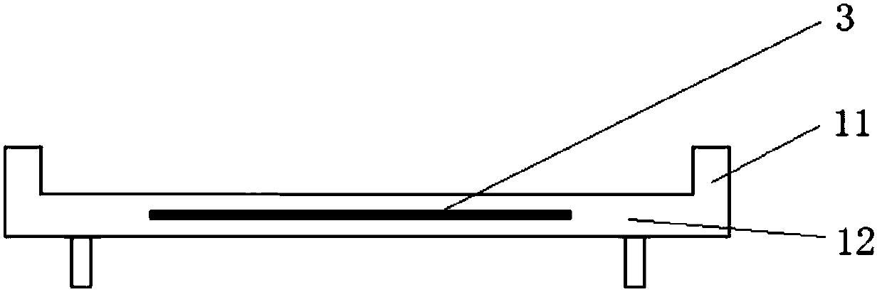
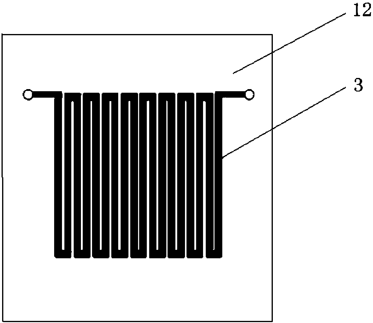
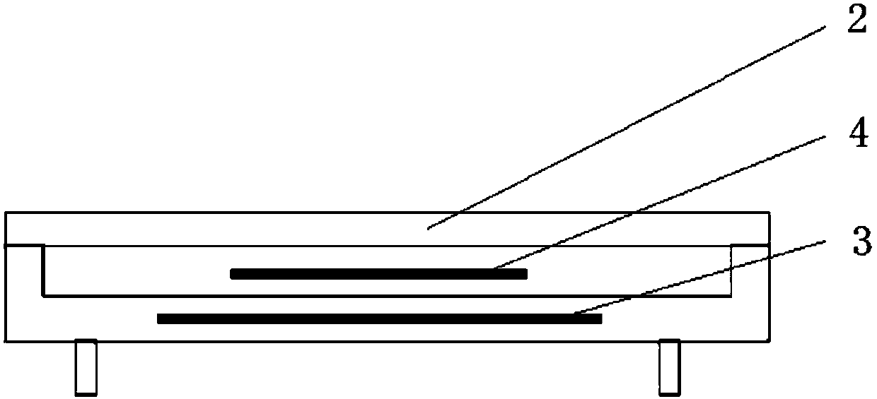
[0026] Please refer to figure 1 , figure 2 with image 3 , figure 1 It is a schematic diagram of the ceramic tube shell structure with built-in heater provided by the present invention, figure 2 for figure 1 Side view of image 3 It is a structural schematic diagram of the ceramic tube shell with built-in heater provided by the present invention when it is in working state.

[0027] The ceramic tube shell with built-in heater provided by the present...


PUM


Abstract

The invention provides a ceramic tube shell of a built-in heater of an infrared detector. The ceramic tube shell of the built-in heater comprises a ceramic tube shell body; and the ceramic tube shellof the built-in heater also comprises a heating device used for heating the ceramic tube shell body and melting the solder arranged between the ceramic tube shell body and a sealing cap, wherein the heating device is embedded inside the ceramic tube shell body. Compared with indirect heat transfer through external equipment in the prior art, the heating device of the ceramic tube shell provided bythe invention is embedded inside the ceramic tube shell body, and can directly heat the ceramic tube shell body; therefore, the heating time of the ceramic tube shell body is shortened, the heating efficiency of the solder is improved, the welding strength between the ceramic tube shell body and the sealing cap is increased, and the solid welding between the ceramic tube shell body and the sealing cap is realized.

Description

technical field [0001] The invention relates to the technical field of MEMS device packaging, in particular to a ceramic shell with a built-in heater. The present invention also relates to an infrared detector comprising the above-mentioned ceramic shell with a built-in heater. Background technique [0002] MEMS device packaging is referred to as Micro-Electro-Mechanical-Systems for short, also known as micro-electromechanical system device packaging. As a kind of MEMS device packaging, ceramic packaging is more and more widely used in equipment such as inertial sensors and infrared detectors because of its advantages of light weight, good airtightness, and low cost. [0003] Generally, the ceramic packaging process is mainly divided into the following steps: [0004] Step 1: Heat the ceramic package product to the hot plate in the welding furnace; [0005] Step 2: heating the ceramic shell through the heat conduction of the hot plate, and melting the solder placed betwee...

Claims


Application Information

Patent Timeline
IPC IPC(8): B81B7/00
CPCB81B7/0032
Inventor 陈文祥张玉佩
Owner IRAY TECH CO LTD
Why Eureka
Try Eureka