
Visual characteristic defogging and image stabilizing detection system

A technology of detection system and visual characteristics, applied in image enhancement, image analysis, image data processing and other directions, can solve the problem of high false alarm rate of algorithm, inability to deal with simultaneous motion of background, and inability to segment objects by difference between frames.

Active Publication Date: 2018-05-18
BEIHANG UNIV
View PDF8 Cites 8 Cited by
  • Summary
  • Abstract
  • Description
  • Claims
  • Application Information

AI Technical Summary

Problems solved by technology

For the inter-frame difference method, when the displacement of the moving target is small, the inter-frame difference cannot segment the target
The inter-frame difference method cannot deal with the problem of simultaneous motion of the background, and cannot isolate the background from the target
The background difference method cannot deal with the background motion problem. When the background continues to move, the background difference method cannot successfully construct the background model, making the difference impossible.
The defect of the motion segmentation method is that the calculation of optical flow will contain more noise, and it is difficult to accurately distinguish the noise from the target when performing optical flow segmentation, resulting in a high false alarm rate of the algorithm
None of these methods have made special processing for the light transmission characteristics of haze, and the processed image has more or less distortion, which affects further enhancement processing.

Method used


Image

  • Visual characteristic defogging and image stabilizing detection system
  • Visual characteristic defogging and image stabilizing detection system
  • Visual characteristic defogging and image stabilizing detection system

Examples


Embodiment Construction

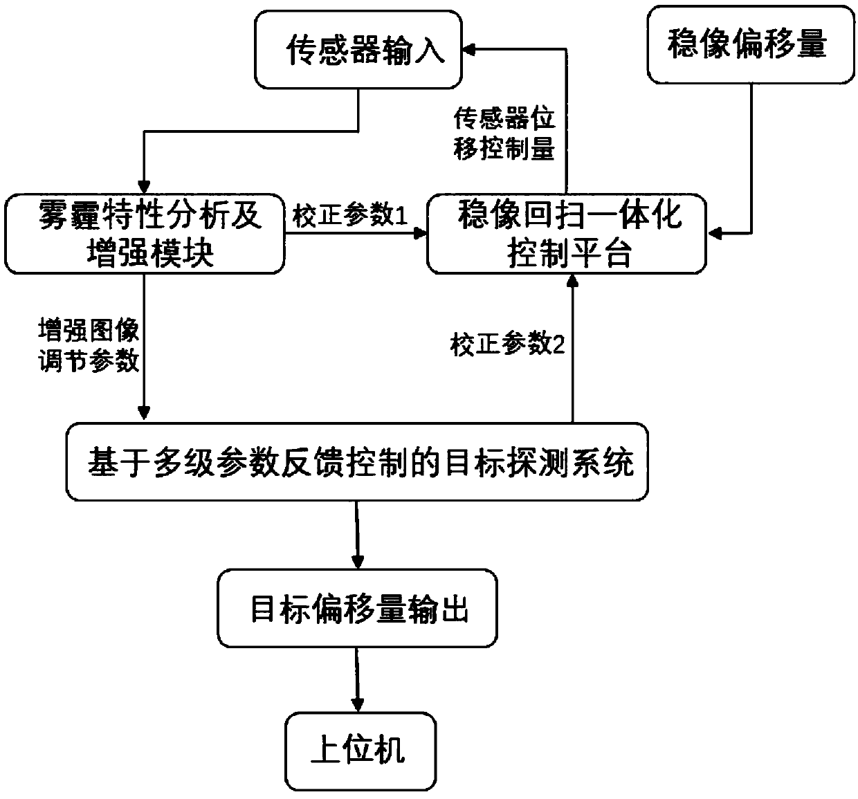
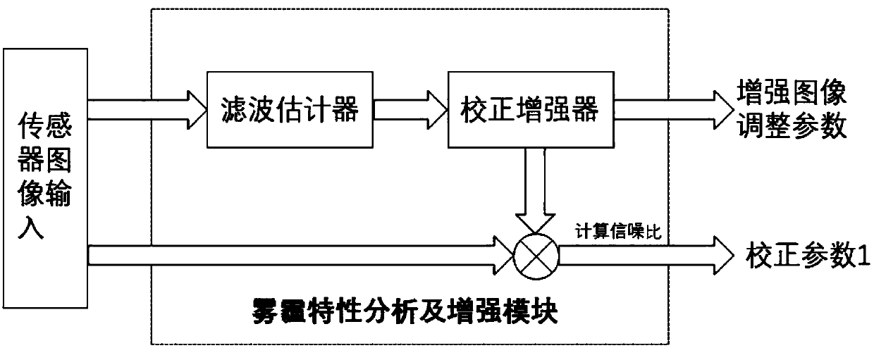
[0135] like figure 1 As shown, the input of the system of the present invention is the image data collected by the front-end sensor, and the image data is first input to the haze characteristic analysis and enhancement module. The haze characteristic analysis and enhancement module uses the color shift estimator to build a dehazing color shift estimation model for the haze-affected imaging image to estimate the color shift of the haze effect and obtain the corrected estimated value. Use this value to equalize and correct the image, and output it to the upper and lower bounds to support the dehazing enhancement filter. The filter adopts the upper and lower bound edge-preserving filter estimator, and calculates the upper and lower bound values ​​of the input corrected image for bidirectional iterative edge-preserving filtering, deepens and corrects the image according to the filtering result, and then uses the inter-frame parameter stabilization filter for smoothing Finally, t...


PUM


Abstract

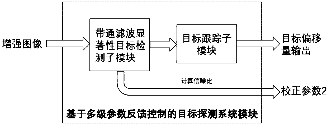
The invention relates to a visual characteristic defogging and image stabilizing detection system including the following modules and functions. First, image data is input into a fog feature analysisand enhancing module and an enhanced image and a correction parameter 1 are acquired through calculation. Second, the enhanced image is input to a multi-level parameter feedback control based object detection system module which calculates out the position of a to-be-detected object through detection and recognition and outputs a target displacement and a correction parameter 2. Third, an image stabilizing displacement calculating module outputs image stabilizing displacement to an image stabilizing flyback integrated control platform. Fourth, the image stabilizing flyback integrated control platform implements an image stabilizing function according to the image stabilizing displacement and adjusts sensor integral time according to the correction parameter 1 and the correction parameter 2. According to the invention, the system implements functions of visual characteristic analysis based defogging enhancement, photoelectric mechanical integrated image stabilization, detection, tracking and the like, achieves good definition, good stability and good accuracy and can be embedded into target detection systems of different types.

Description

technical field [0001] The invention relates to a visual characteristic defogging and image stabilization detection system, which belongs to the interdisciplinary field of automatic control and electronic information. Background technique [0002] Target tracking refers to the task of giving the position of the target in a certain frame of the video, and then the algorithm continuously calculates the target position in the subsequent frames. At present, one of the mainstream target tracking algorithms is based on the target detection method. The commonly used detection methods include inter-frame difference, background difference and motion segmentation. The inter-frame difference uses the change between frames to realize the detection, and the common method is two-frame or three-frame difference method. The background difference method uses the background image or reconstructs the background through the model, and obtains the moving target area by difference with the curre...

Claims


Application Information

Patent Timeline
Patent Type & Authority Applications(China)
IPC IPC(8): G06T5/00G06T7/246
CPCG06T7/246G06T2200/28G06T2207/10016G06T5/73
Inventor 张弘杨一帆李伟鹏袁丁
Owner BEIHANG UNIV
Learn More