Multifunctional rope releasing device

A multifunctional and equipment technology, applied in the fields of fire extinguishing, rescue and escape equipment outside the building, it can solve the problems that the fire hydrant door is blocked by residents' sundries, affecting the speed and efficiency of rescue and fire extinguishing, and incomplete fire protection facilities, etc.

Inactive Publication Date: 2018-05-22
福州欧普曼自动化设备有限公司
View PDF0 Cites 1 Cited by
  • Summary
  • Abstract
  • Description
  • Claims
  • Application Information

AI Technical Summary

Problems solved by technology

There is also the arm-raising fire truck used in the existing fire-fighting and lifesaving, which can generally implement fire fighting and rescue at a height of 53 meters, and the climbing of the fire-fighting ladder truck has a limit. Usually, the fire-fighting ladder truck can only rise to 80 of the limit value. % or so, if the wind force on the ground reaches level 4 to 5, the fire-fighting aerial ladder truck will not be able to raise the operation. In this way, once a high-rise building above 50 meters catches fire or people are trapped, it will be difficult for the fire-fighting aerial ladder to play a role. Rely on one's own ability to escape, but some high-rise buildings have incomplete fire-fighting facilities, fire hydrant doors are blocked by residents with sundries and other phenomena, which bring resistance to f

Method used


Image

  • Multifunctional rope releasing device
  • Multifunctional rope releasing device
  • Multifunctional rope releasing device

Examples


Embodiment Construction

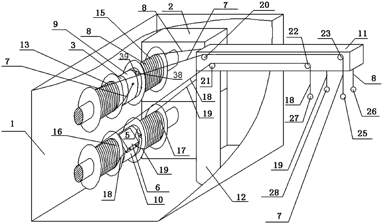
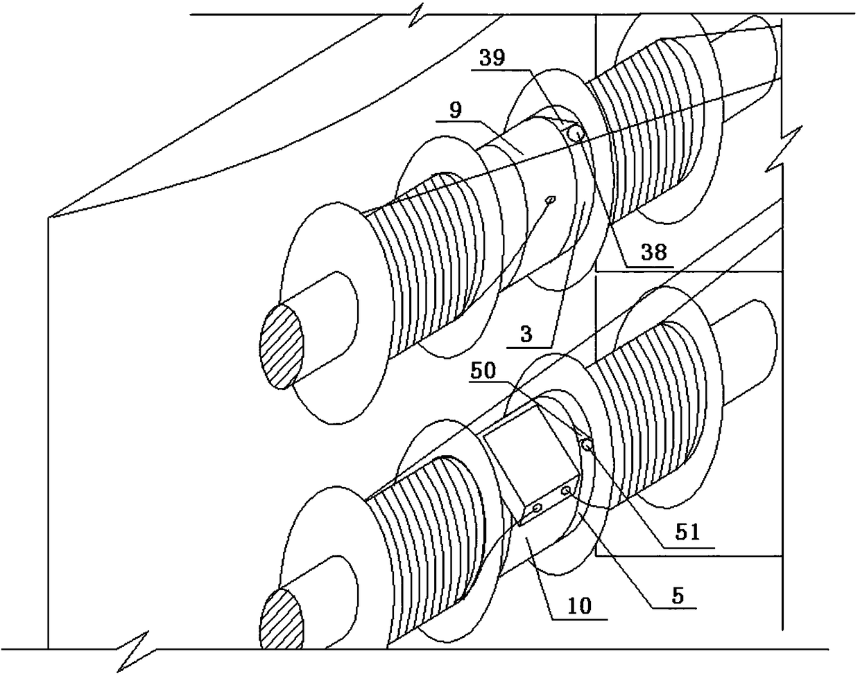
[0104] like figure 1 as shown, figure 1 It is a schematic diagram of the oblique view of the first embodiment of the present application. The multifunctional rope releasing device includes a housing 1, an electric motor 2, a reel 3, a reel 5, a descender 6, a pull rope 7, a pull rope 8, a ring 9, a ring 10, a cantilever 11, and a column 12 , the above-mentioned electric motor 2, reel 3, reel 5, slow descender 6, stay rope 7, stay rope 8, ring 9, ring 10, column 12 are arranged in the housing, electric motor 2 and reel 3, The connection of the reel 5 can drive the reel 3 and the reel 5 to rotate. The above-mentioned ring 9 is set on the outer periphery of the reel 3 and can rotate around the reel 3. The above-mentioned ring 10 is set on the outer periphery of the reel 5 and can surround the reel 5 rotation, the above-mentioned descending device 6 is arranged on the ring 10, and one end of the above-mentioned stay rope 7 and stay rope 8 is fixedly connected on the ring 9. T...


PUM


Abstract

Provided is a multifunctional rope releasing device. The multifunctional rope releasing device comprises a power transmission system or a hydraulic transmission system or a pneumatic transmission system, a reel or a rotating shaft, and a descent control device. A rotating shaft of a motor of the power transmission system or the hydraulic transmission system or the pneumatic transmission system candrive the reel or the rotating shaft to rotate through a transmission mechanism. The motor is an electric motor or a hydraulic motor or a pneumatic motor. The power transmission system comprises theelectric motor. A round ring is sleeved on the reel or the rotating shaft. The round ring can rotate around the reel or the rotating shaft. The round ring is provided with a blocking surface. The reelor the rotating shaft is provided with a blocking piece. The descent control device is arranged on the round ring. A slow descent rope of the descent control device extends out from the descent control device and is coiled on the reel or the rotating shaft, and a cable connected with the electric motor or a motor or a magnetic exchange valve is connected with a power supply through an electricalcontrol system.

Description

technical field [0001] The application belongs to a kind of outdoor fire extinguishing, rescue and escape equipment used in the construction field. Background technique [0002] Fires in high-rise buildings have always attracted people's attention, and the reliability of fire elevators in the event of a fire is worth pondering. There is also the arm-raising fire truck used in the existing fire-fighting and lifesaving, which can generally implement fire fighting and rescue at a height of 53 meters, and the climbing of the fire-fighting ladder truck has a limit. Usually, the fire-fighting ladder truck can only rise to 80 of the limit value. % or so, if the wind force on the ground reaches level 4 to 5, the fire-fighting aerial ladder truck will not be able to raise the operation. In this way, once a high-rise building above 50 meters catches fire or people are trapped, it will be difficult for the fire-fighting aerial ladder to play a role. Rely on one's own ability to escape...

Claims


Application Information

Patent Timeline
IPC IPC(8): A62B1/10A62B1/12A62B1/18A62C31/00
CPCA62B1/10A62B1/12A62B1/18A62C31/00
Inventor 不公告发明人
Owner 福州欧普曼自动化设备有限公司
Why Eureka
Try Eureka