Fast new energy vehicle charging pile

A technology for new energy vehicles and charging piles, which is applied to electric vehicle charging technology, charging stations, electric vehicles, etc., can solve the problems of difficulty in removing the charging cable reel, occupying internal space, uneven coiling, etc., to improve work efficiency. The effect of speed, improved uniformity and easy maintenance

Inactive Publication Date: 2018-05-25
CIXI QICHENG MACHINERY TECH CO LTD
View PDF0 Cites 3 Cited by
  • Summary
  • Abstract
  • Description
  • Claims
  • Application Information

AI Technical Summary

Problems solved by technology

After charging the electric vehicle with the charging gun on the charging pile, the user needs to retract the pulled power cord into the charging pile. The traditional manual coiling method is time-consuming and laborious, and some charging piles with automatic coiling function will be damaged when coiling. Uneven coiling occurs, occupying internal space, and it is difficult to remove the charging cable reel for maintenance and replacement of aging charging cables

Method used


Image

  • Fast new energy vehicle charging pile
  • Fast new energy vehicle charging pile
  • Fast new energy vehicle charging pile

Examples


Embodiment Construction

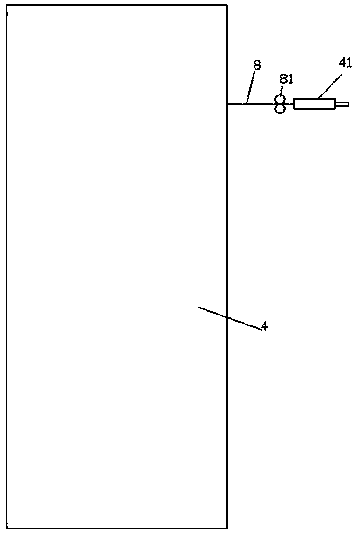
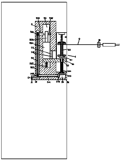
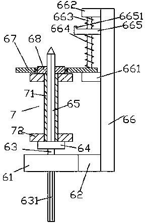
[0022] like Figure 1-Figure 5 As shown, a fast new energy vehicle charging pile of the present invention includes a machine column 5 arranged inside the charging pile 4 and a finishing wheel 81 arranged on the right side of the machine column 5 and arranged up and down equally. A base 51 is provided at the bottom of the right side of the column 5, and a charging wire coiling device 6 is provided above the base 51, and the charging wire coiling device 6 includes sliding joint plates 61 extending left and right, fixed on the sliding joint The middle block 62 on the rear side of the plate 61, the wall plate 66 fixed on the rear side of the middle block 62 and extended upward, and the coil seat 64 arranged above the sliding joint plate 61, the bottom of the coil seat 64 is fixed There is a first rotating rod 63, the bottom of the first rotating rod 63 passes through the sliding joint plate 61 and is rotatably connected, and the bottom of the first rotating rod 63 is fixed with an...


PUM


Abstract

The invention discloses a fast new energy vehicle charging pile. The fast new energy vehicle charging pile comprises a machine column and finishing wheels, wherein the machine column is arranged in the charging pile, and the finishing wheels are arranged on the right side of the machine column, and are arranged in a up and down mode with equal distance. The bottom of the right side of the machinecolumn is provided with a base platform. A charging wire coiling device is arranged above the base platform. The charging wire coiling device comprises a sliding joint plate, a middle block; a wall plate and a coiling seat, wherein the sliding joint plate is arranged in a left and right extending mode; the middle block is fixedly arranged on the back side of the sliding joint plate; the wall plateis fixedly arranged on the back side of the middle block, and is arranged in an upward extending mode; and the coiling seat is arranged above the sliding joint plate. The bottom of the coiling seat is fixedly provided with a first rotating rod. The bottom of the first rotating rod penetrates through the sliding joint plate, and is connected with the sliding joint plate in a rotating and matched mode. An external spline shaft is fixedly arranged on the bottom of the first rotating rod, and is arranged in a downward extending mode. A screw-shape rod is fixedly arranged on the top of the coilingseat. A first conversion cavity is formed in the base platform. An inner spline shaft is connected with the top wall of the first conversion cavity in a rotating and matched mode, and is arranged inan upward and downward extending mode. The fast new energy vehicle charging pile has simple structure; the automatic control towards up and down mobile charging line coiling work is achieved; the uniformity of the coiling of the charging wire is improved; the fast disassembly towards a reel is achieved; and the coiling stability of the charging line is improved.

Description

technical field [0001] The invention relates to the field of charging piles, in particular to a fast charging pile for new energy vehicles. Background technique [0002] As the number of automobiles in our country continues to grow, the harm to the environment is becoming more and more serious. Countries around the world are beginning to encourage the purchase of new energy vehicles, and the charging pile industry is also booming. After charging the electric vehicle with the charging gun on the charging pile, the user needs to retract the pulled power cord into the charging pile. The traditional manual coiling method is time-consuming and laborious, and some charging piles with automatic coiling function will be damaged when coiling. Uneven coiling occurs, occupying internal space, and it is difficult to remove the charging cable reel for maintenance and replacement of aging charging cables. Contents of the invention [0003] The technical problem to be solved by the pres...

Claims


Application Information

Patent Timeline
Patent Type & Authority Applications(China)
IPC IPC(8): B60L11/18H01R13/72
CPCB60L53/31H01R13/72Y02T10/70Y02T10/7072Y02T90/12
Inventor 姚瑞波
Owner CIXI QICHENG MACHINERY TECH CO LTD
Why Eureka
Try Eureka