Structure and assembling technology of propeller blade connecting joint

A technology for connecting joints and blades, applied in the field of helicopter main propeller hub structure design and assembly, can solve problems such as affecting flight safety, attendance, loose or fretting bushings with large shoulders, and difficult to replace, etc., so as to avoid bushings. Slip problem, prevent initial damage, avoid the effect of force falling off

Inactive Publication Date: 2018-05-25
CHANGHE AIRCRAFT INDUSTRIES CORPORATION
View PDF6 Cites 5 Cited by
  • Summary
  • Abstract
  • Description
  • Claims
  • Application Information

AI Technical Summary

Problems solved by technology

The bumping of the shoulder during the installation of the propeller may cause loosening or fretting of the large shoulder bushing, and at the same time, the bumping damage is not easy to replace, thus affecting the life of the hole, reliability and structural maintainability
The other is that the straight bushing is installed in the hole through temperature difference assembly, and then the large gasket is bonded to the end face of the hole with an adhesive, such as figure 2 , the bushing is a straight bushing, and the force transmission gasket and the guide gasket are combined into a large gasket. In the actual use process, the straight bush often has the bushing slippage, and the large gasket is degummed and falls o...

Method used


Image

  • Structure and assembling technology of propeller blade connecting joint
  • Structure and assembling technology of propeller blade connecting joint
  • Structure and assembling technology of propeller blade connecting joint

Examples


Embodiment Construction

[0027] The present invention will be described in further detail below.

[0028] Step 1: First Extrusion Strengthening

[0029] 1) Check the parts and equipment before extrusion, and set the extrusion parameters;

[0030] 2) Apply the dry film lubricant GH-51 on the inner wall of the connection hole 4 of the paddle connection structure repeatedly and evenly for three layers;

[0031] 3) After the dry film lubricant is solidified, use the extrusion equipment and the extrusion mandrel to complete the first extrusion strengthening of the hole;

[0032] Step 2: Second Extrusion Strengthening

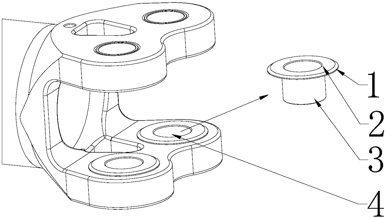
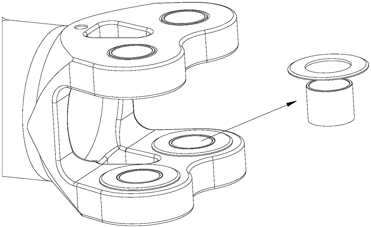
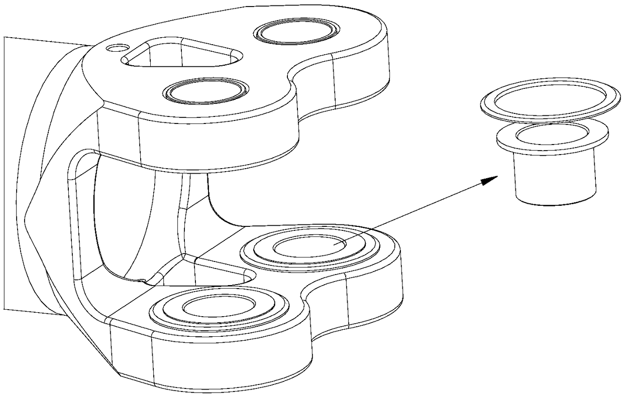
[0033] 1) Apply dry film lubricant GH-51 to the inner wall of the bushing hole 3 repeatedly and evenly for three layers;

[0034] 2) After the dry film lubricant is solidified, use extrusion equipment and extrusion mandrels to complete the extrusion strengthening assembly of the bushing 3;

[0035] 3) The gap between the shoulder of the small shoulder bush and the end face of the hole af...


PUM


Abstract

The invention belongs to the technical field of structural design and assembling technologies of main propeller hubs of helicopters, and particularly relates to a structure and assembling technology of a propeller blade connecting joint. At present, one structure is to assemble and mount a lining with a large protruding shoulder into a hole through the temperature difference, the other structure is to assemble and mount a straight lining into the hole through the temperature difference, and then a large gasket is bonded to the hole end face through an adhesive agent. The linings of the two connecting joints adopt the mode of temperature difference assembly, initial damage of the inner surface of the hole has uncertainty, binding force of the hole and the lining is small, and the hole and the lining are prone to generating fretting wear after the hole is subjected to force. According to the structure of the propeller blade connecting joint, a lining is mounted in a connecting hole, thelining is provided with a protruding shoulder, the lining is mounted in the connecting hole through a secondary extruding strengthening method, the lining is used for transmitting the force, and the width of the protruding shoulder of the lining is smaller than 10 mm; and a guiding gasket is arranged on the periphery of the protruding shoulder, the easily occurred problem of sliding of the liningcan be avoided, and meanwhile, the problem of upwarp by excessively extruding strengthening assembly of the protruding shoulder is solved.

Description

technical field [0001] The invention belongs to the technical field of structural design and assembly of a main rotor hub of a helicopter, and in particular relates to a structure and an assembly process of a blade connecting joint. Background technique [0002] At present, the newly developed main propeller hub of the helicopter adopts a spherical flexible structure, and the propeller and the support arm are connected by a propeller pin. The shimmy and torsional force are the bottlenecks of the life of the support arm. [0003] At present, there are mainly two structures, one is that the large shoulder bush is installed in the hole through temperature difference assembly, such as figure 1 A bushing 3 is installed in the connecting hole 4 of the paddle joint, and the shoulder of the bushing 3 has a force transmission area 2 and a guiding area 1. The force-bearing and force-transmitting part of the vibration; the force-transmitting area 2 is in contact with the blade, and i...

Claims


Application Information

Patent Timeline
IPC IPC(8): B64C27/48B64F5/10
CPCB64C27/48
Inventor 胡超鹏李萌汪广平汤明军苏贵鸿赵越黄康华屈新河应少军郑雷
Owner CHANGHE AIRCRAFT INDUSTRIES CORPORATION
Why Eureka
Try Eureka