

Hydrocracking method
A hydrocracking and hydrofining technology, which is applied in the fields of hydrotreating process, petroleum industry, and hydrocarbon oil treatment, can solve problems such as easy clogging and increased pressure drop in reactors, so as to prevent clogging, avoid pressure drop, prolong The effect of turning head time
- Summary
- Abstract
- Description
- Claims
- Application Information
AI Technical Summary
Problems solved by technology
Method used
Image

Examples
Embodiment 1
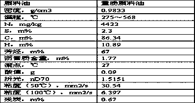
[0038] The raw material of heavy distillate oil (see Table 1 for properties, the raw material used in the following examples and comparative examples) is mixed with hydrogen and then enters the hydrofining reactor, hydrocracking reactor and separation system in sequence, and light naphtha, Heavy naphtha, aviation kerosene fraction, diesel fraction and hydrocracking tail oil, the upper part of the hydrotreating reactor is provided with a cylinder with a bottom, and the height of the cylinder is 5% of the height of the hydrotreating reactor. The outer diameter is 95% of the inner diameter of the hydrotreating reactor. There are holes on the bottom and side wall of the cylinder to allow the flow to pass through. The size of the hole is 5 mesh. The cylinder is filled with hydrotreating catalysts along the flow direction A, hydrofining catalyst B, the loading volume ratio is 1:5, the properties of the hydrofining catalyst A are as follows: the amount of infrared acid is 0.4mmol / g, t...
Embodiment 2
[0040] The raw material of heavy distillate oil (see Table 1 for properties, the raw material used in the following examples and comparative examples) is mixed with hydrogen and then enters the hydrofining reactor, hydrocracking reactor and separation system in sequence, and light naphtha, Heavy naphtha, aviation kerosene fraction, diesel fraction and hydrocracking tail oil, the upper part of the hydrofinishing reactor is provided with a cylinder with a bottom, and the height of the cylinder is 20% of the height of the hydrofinishing reactor. The outer diameter is 90% of the inner diameter of the hydrofining reactor, and there are holes on the bottom and side wall of the cylinder to allow the flow to pass through. A, hydrofining catalyst B, the loading volume ratio is 1:3, the properties of the hydrofining catalyst A are as follows: the amount of infrared acid is 0.45mmol / g, the pore volume is 0.55ml / g, and the particle diameter of the catalyst is 5.5 mm, with a specific surfa...
Embodiment 3
[0042] The raw material of heavy distillate oil (see Table 1 for properties, the raw material used in the following examples and comparative examples) is mixed with hydrogen and then enters the hydrofining reactor, hydrocracking reactor and separation system in sequence, and light naphtha, Heavy naphtha, aviation kerosene fraction, diesel fraction and hydrocracking tail oil, the upper part of the hydrofinishing reactor is provided with a cylinder with a bottom, and the height of the cylinder is 15% of the height of the hydrofinishing reactor. The outer diameter is 85% of the inner diameter of the hydrotreating reactor. There are holes on the bottom and side wall of the cylinder to allow the flow to pass through. The size of the hole is 15 mesh. The cylinder is filled with hydrotreating catalysts along the flow direction A, hydrofining catalyst B, the loading volume ratio is 3:1, the properties of the hydrofining catalyst A are as follows: the amount of infrared acid is 0.5mmol / ...
PUM
| Property | Measurement | Unit |
|---|---|---|
| Pore volume | aaaaa | aaaaa |
| Particle size | aaaaa | aaaaa |
| Specific surface area | aaaaa | aaaaa |
Abstract
Description
Claims
Application Information