FPGA static timing analysis algorithm

A static timing analysis and algorithm technology, applied in computing, CAD circuit design, special data processing applications, etc., to reduce logic and wiring delays and increase operating frequency

Active Publication Date: 2018-05-25
NO 47 INST OF CHINA ELECTRONICS TECH GRP
View PDF5 Cites 7 Cited by
  • Summary
  • Abstract
  • Description
  • Claims
  • Application Information

AI Technical Summary

Problems solved by technology

[0004] At present, the domestic timing analysis field lacks an accurate timing analysis method for analyzing various delay paths

Method used


Image

  • FPGA static timing analysis algorithm

Examples


Embodiment Construction

[0023] The present invention will be further described in detail below in conjunction with the examples.

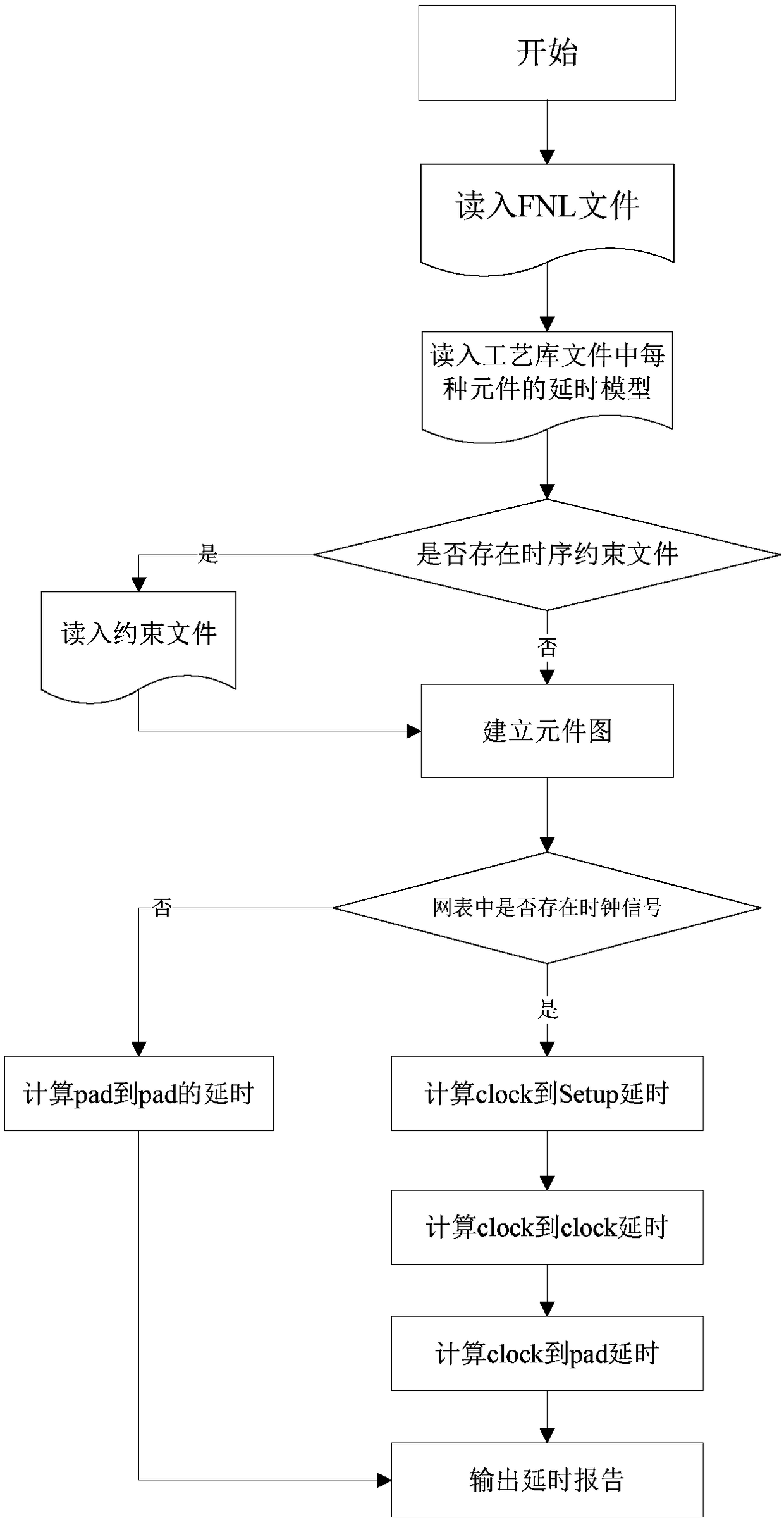
[0024] Such as figure 1 As shown, the present invention relates to an algorithm for FPGA static timing analysis. The purpose of this algorithm is to find the critical paths that make chip timing invalid and play a decisive role in chip performance faster. It uses an exhaustive analysis method (existing method) to extract all timing paths that exist in the entire circuit, examine whether the signal meets the requirements of timing constraints when passing through these paths, and find out violations by analyzing the maximum path delay and the minimum path delay. Timing constraint error.

[0025] The key point of the design of timing analysis program is the establishment of directed acyclic graph (hereinafter referred to as graph) and the calculation of critical path. First, the establishment of the graph is divided into two stages. After each element is read in and a no...


PUM


Abstract

The invention relates to an FPGA static timing analysis algorithm which specifically comprises the steps of extracting all timing paths existing in an entire circuit, checking whether signals meet therequirements of timing constraints when passing through the paths, and finding errors violating the timing constraints by analyzing a maximum path delay and a minimum path delay. According to the method, a critical path that makes the chip timing fail and has a decisive effect on the chip performance can be found more quickly.

Description

technical field [0001] The invention is mainly used in the static timing analysis field of FPGA. Under the premise of providing logic units, corresponding connection relationships and known chip structures, timing analysis can be performed on specified netlist circuits. Background technique [0002] The premise of static timing analysis is that the designer first puts forward the requirements, and then the timing analysis tool will analyze according to the specific timing model and give the correct timing report. [0003] The main purpose of static timing analysis is to improve the main frequency of the system and increase the stability of the system. For many digital circuit designs, it is very important to increase the operating frequency, because high operating frequency means high processing power. Synthesis, mapping, placement, and routing of logic can be controlled through additional constraints to reduce logic and routing delays and thus increase operating frequency...

Claims


Application Information

Patent Timeline
Patent Type & Authority Applications(China)
IPC IPC(8): G06F17/50
CPCG06F30/3312G06F30/34
Inventor 杨兴张海涛
Owner NO 47 INST OF CHINA ELECTRONICS TECH GRP
Why Eureka
Try Eureka