Power battery base tray and power battery module
A power battery pack, power battery technology, applied in battery pack components, batteries, secondary batteries, etc., can solve the problems of low efficiency in assembly and disassembly of liquid cooling tubes, avoid mechanical strength drop, increase supporting load, improve The effect of cooling efficiency
- Summary
- Abstract
- Description
- Claims
- Application Information
AI Technical Summary
Problems solved by technology
Method used
Image

Examples
Embodiment 1
[0031] An embodiment of the present invention provides a power battery bottom support for supporting a power battery pack.
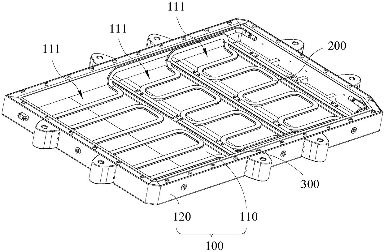
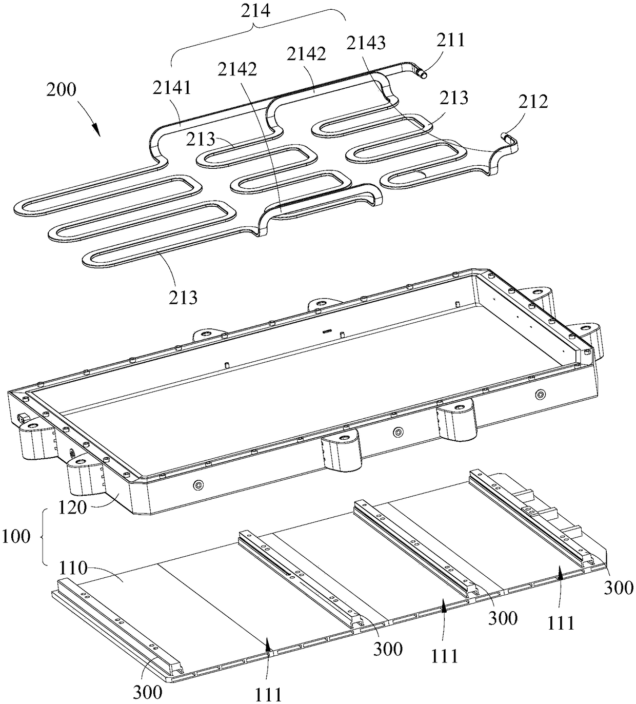
[0032] Such as figure 1 with figure 2 As shown, the power battery base includes a tray 100 and a liquid cooling tube 200 installed on the tray 100 . Wherein, the liquid cooling tube 200 may be made of materials with high thermal conductivity, such as metal copper, metal silver, and the like. The tray 100 includes a bottom plate 110 and side plates 120 arranged around the bottom plate 110. The bottom plate 110 and the side plates 120 together form an accommodating cavity (not marked in the figure) for accommodating a power battery pack. At least one beam 300 is arranged on the bottom plate 110. A transverse beam 300 may preferably be arranged across. Each beam 300 divides the base plate 110 into at least two sub-base plates 111, the liquid cooling tube 200 is laid on at least one of the sub-base plates 111, and the liquid cooling tube 200 straddles th...
Embodiment 2
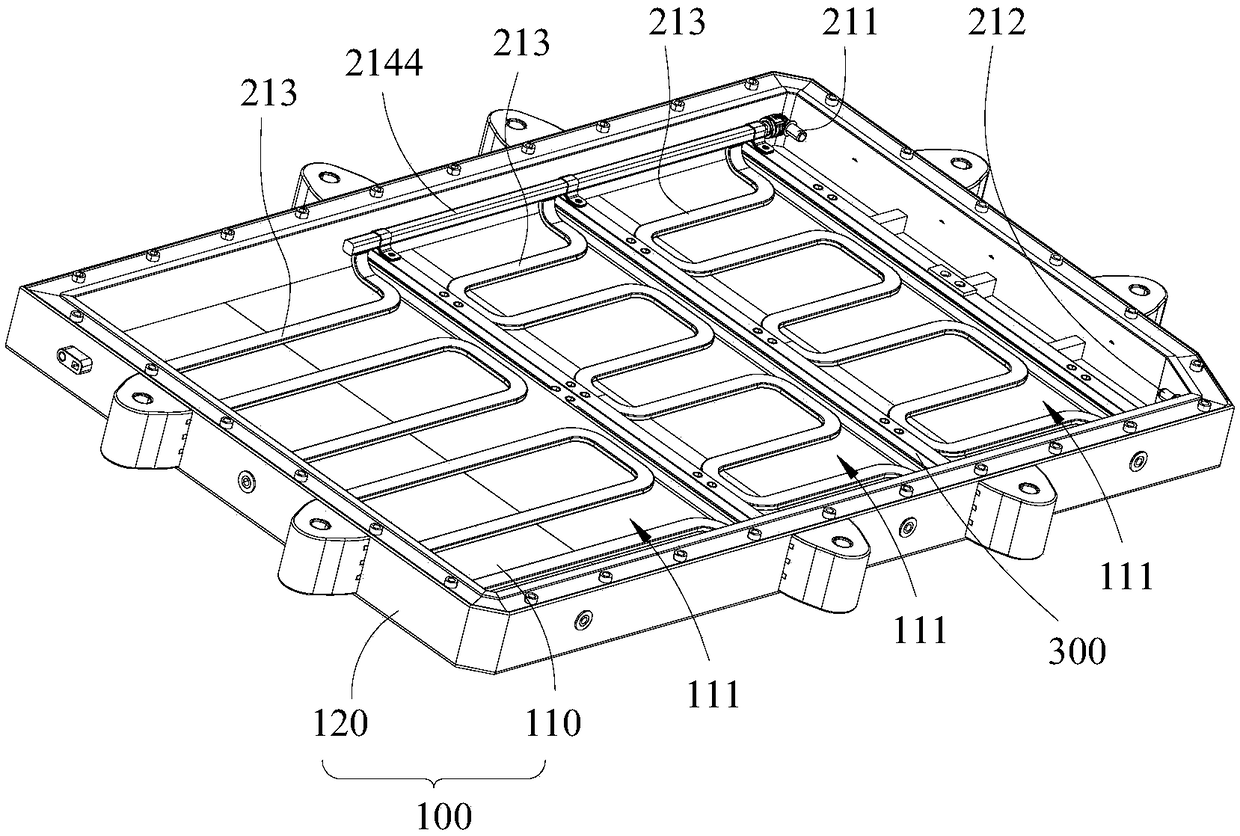
[0048] like image 3 As shown, the difference between the second embodiment and the first embodiment lies in the connecting pipe set 214. Specifically, the connecting pipe set 214 includes two confluence pipes 2144, wherein one confluence pipe 2144 communicates with the liquid inlet pipe 211, and the other confluence pipe 2144 communicates with the liquid outlet pipe 212, and the two confluence pipes 2144 straddle the crossbeams 300 they pass through respectively. Specifically, one end of the fitting pipe 213 communicates with a confluence pipe 2144, and the other end communicates with another confluence pipe 2144; at the same time, the above-mentioned fitting pipe 213 includes at least two, so that at least two fitting pipes 213 are arranged in parallel, When the medium enters the bonding pipes 213 arranged in parallel through a confluence pipe 2144 , they all have approximately the same temperature, which is beneficial to balance the heat absorption capacity of the bonding p...
Embodiment 3
[0052] The difference between the third embodiment and the second embodiment lies in the connecting tube group, which also includes a fourth connecting tube for connecting the two laminating tubes, the fourth connecting tube straddles the crossbeam it passes through, and the fourth connecting tube is at least There is one, that is, at least two bonding tubes are connected in series before they are connected to the manifold instead of being directly connected to the two manifolds. Based on this structure, the liquid cooling tube has bonding tubes arranged in series and parallel. The fitting tubes arranged in this way are beneficial to comprehensively utilize the advantages of the fitting tubes being arranged in series and in parallel, and can be arranged according to specific heat dissipation requirements.
PUM
 Abstract
Description
Claims
Application Information
 - R&D
- Intellectual Property
- Life Sciences
- Materials
- Tech Scout
- Unparalleled Data Quality
- Higher Quality Content
- 60% Fewer Hallucinations
Browse by: Latest US Patents, China's latest patents, Technical Efficacy Thesaurus, Application Domain, Technology Topic, Popular Technical Reports.
© 2025 PatSnap. All rights reserved.Legal|Privacy policy|Modern Slavery Act Transparency Statement|Sitemap|About US| Contact US: help@patsnap.com