Current-limiting blockout device and method of DC power distribution network

A technology of DC power distribution network and DC power distribution, applied in the direction of DC network circuit devices, circuit devices, emergency protection circuit devices for limiting overcurrent/overvoltage, etc. The problems of high loss and manufacturing cost, to achieve the effect of fast blocking and reducing impact

Active Publication Date: 2018-05-25
INST OF ELECTRICAL ENG CHINESE ACAD OF SCI
View PDF6 Cites 2 Cited by
  • Summary
  • Abstract
  • Description
  • Claims
  • Application Information

AI Technical Summary

Problems solved by technology

The circuit breaker is completely composed of semiconductor devices, and its application in the field of high-voltage direct current transmission is limited by the disadvantages of high on-state loss, high manufacturing cost, low withstand voltage and complex control.

Method used


Image

  • Current-limiting blockout device and method of DC power distribution network
  • Current-limiting blockout device and method of DC power distribution network
  • Current-limiting blockout device and method of DC power distribution network

Examples


Embodiment 1

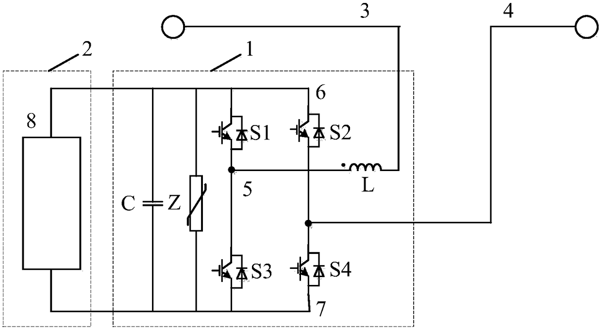
[0042] figure 1 Shown is Example 1 of the present invention. Such as figure 1 As shown, the DC current-limiting breaking device of the present invention includes: a current-limiting blocking circuit 1 and a pre-charging circuit 2; the current-limiting blocking circuit includes a first capacitor C, a first arrester Z, a first power electronic switching device S1, the second power electronic switching device S2, the third power electronic switching device S3, the fourth power electronic switching device S4 and the first current limiting inductor L are connected in series to the DC power distribution line; the pre-charging circuit 2 includes the first pre-charging circuit Charging device 8.

[0043] The second lead-out terminal of the first current-limiting inductance L is connected at the third connection point 3 of the DC distribution line; the second lead-out terminal of the second power electronic switching device S2 and the first lead-out terminal of the fourth power elect...

Embodiment 2

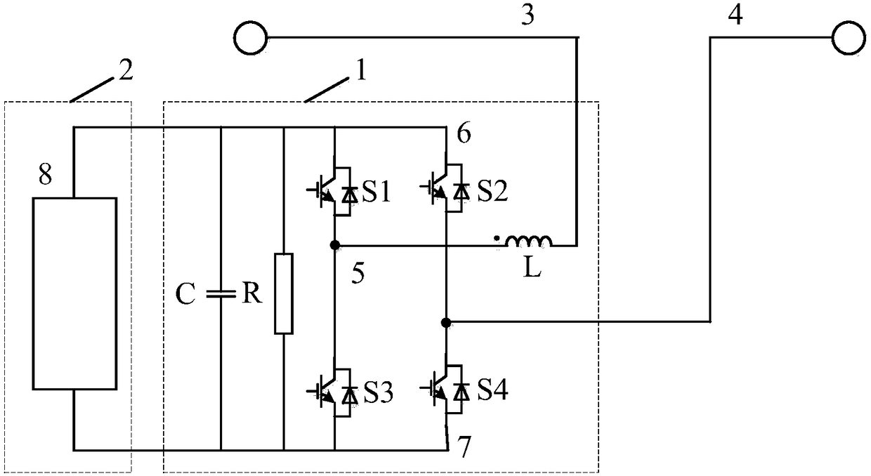
[0054] figure 2 Shown is Example 2 of the present invention. Such as figure 2 As shown, the DC current-limiting breaking device of the present invention includes: a current-limiting blocking circuit 1 and a pre-charging circuit 2; the current-limiting blocking circuit includes a first capacitor C, a first discharge resistor R, a first power electronics The switching device S1, the second power electronic switching device S2, the third power electronic switching device S3, the fourth power electronic switching device S4 and the first current-limiting inductor L are connected in series to the DC power distribution line; the pre-charging circuit 2 includes the first A pre-charging device 8 .

[0055] The second lead-out terminal of the first current-limiting inductance L is connected at the third connection point 3 of the DC distribution line; the second lead-out terminal of the second power electronic switching device S2 and the first lead-out terminal of the fourth power el...

Embodiment 3

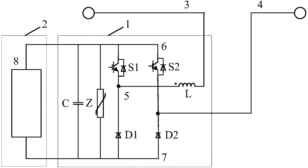
[0062] image 3 Shown is Example 3 of the present invention. Such as image 3 As shown, the DC current-limiting breaking device of the present invention includes: a current-limiting blocking circuit 1 and a pre-charging circuit 2; the current-limiting blocking circuit includes a first capacitor C, a first arrester Z, a first power electronic switching device S1, the second power electronic switching device S2, the first diode D1, the second diode D2 and the first current-limiting inductor L are connected in series to the DC power distribution line; the pre-charging circuit 2 includes a first pre-charging device 8 .

[0063] The second lead-out terminal of the first current-limiting inductance L is connected at the third connection point 3 of the DC distribution line; the second lead-out terminal of the second power electronic switching device S2 and the first lead-out terminal of the second diode D2 are connected at the DC distribution line The fourth connection point 4 of ...


PUM


Abstract

The invention relates to a current-limiting blockout device and method of a DC power distribution network. The device is composed of a current-limiting blockout loop (1) and a pre-charging circuit (2). The fault current-limiting blockout loop (1) is composed of a first capacitor (C), a first lightning arrester (Z), a first power electronic switch device (S1), a second power electronic switch device (S2), a third power electronic switch device (S3), a fourth power electronic switch device (S4) and a first current-limiting inductor (L). Thus, a fault current in the DC power distribution networkcan be limited and blocked rapidly, and impact of the fault current on a power supply and loads is greatly reduced in the DC power distribution network.

Description

technical field [0001] The invention relates to a current limiting and blocking device and method for a direct current distribution network, belonging to the technical field of direct current distribution networks. Background technique [0002] Considering the continuous access of DC loads such as energy storage systems, electric vehicle charging stations, and information data centers in medium-voltage distribution networks, the DC distribution network technology with high reliability and high power quality will have a good application prospect in the field of power distribution. DC circuit breakers, DC / DC converters and DC current limiters for DC distribution networks are key equipment for building DC distribution networks. Due to the low voltage level of the DC distribution network demonstration projects that have been built at home and abroad, they mainly study the system architecture, control and protection of the DC distribution network, and have less research on DC equ...

Claims


Application Information

Patent Timeline
Patent Type & Authority Applications(China)
IPC IPC(8): H02H9/02H02J1/00
CPCH02H9/005H02H9/02H02J1/00
Inventor 尹靖元吴理心霍群海韦统振
Owner INST OF ELECTRICAL ENG CHINESE ACAD OF SCI
Why Eureka
Try Eureka