
Using method of numerical control laser cutting device

A cutting device, numerical control laser technology, applied in laser welding equipment, welding equipment, metal processing equipment and other directions, can solve the problems of inconvenient operator control, physical injury of operators, complicated operation procedures, etc., to save manpower, prevent Injury to the human body, the effect of ensuring safety

Inactive Publication Date: 2018-05-29
王余江
View PDF0 Cites 3 Cited by
  • Summary
  • Abstract
  • Description
  • Claims
  • Application Information

AI Technical Summary

Problems solved by technology

[0002] CNC laser cutting machine is to focus the laser emitted from the laser into a high power density laser beam through the optical path system. During the cutting process of the current CNC laser cutting machine, the high-intensity light will cause damage to the human eye and at the same time The skin will also be burned to a certain extent, and the toxic gas generated during the cutting process will also cause great harm to the operator's body, and the current method of using the CNC laser cutting device has complicated operating procedures and is not easy for the operator to operate and control

Method used


Image

  • Using method of numerical control laser cutting device
  • Using method of numerical control laser cutting device
  • Using method of numerical control laser cutting device

Examples


Embodiment Construction

[0029] The following will clearly and completely describe the technical solutions in the embodiments of the present invention with reference to the accompanying drawings in the embodiments of the present invention. Obviously, the described embodiments are only some, not all, embodiments of the present invention. Based on the embodiments of the present invention, all other embodiments obtained by persons of ordinary skill in the art without making creative efforts belong to the protection scope of the present invention.

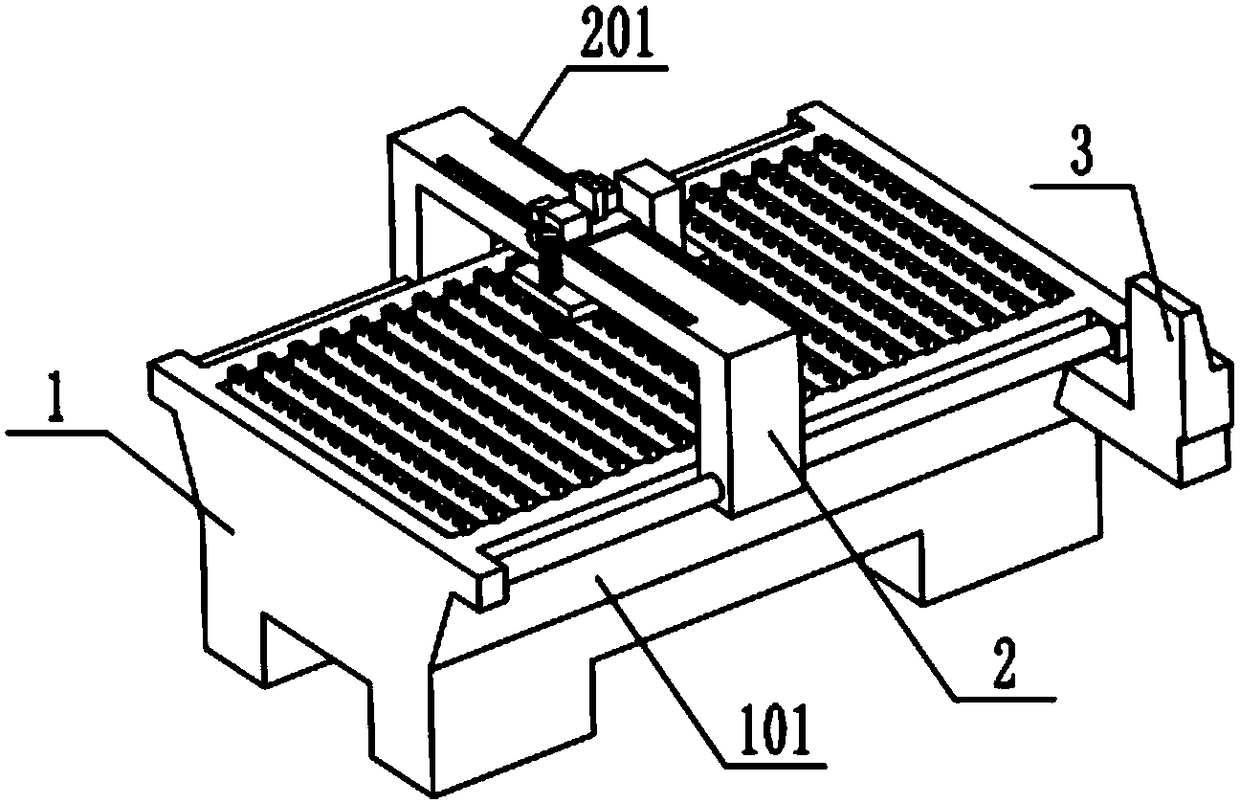
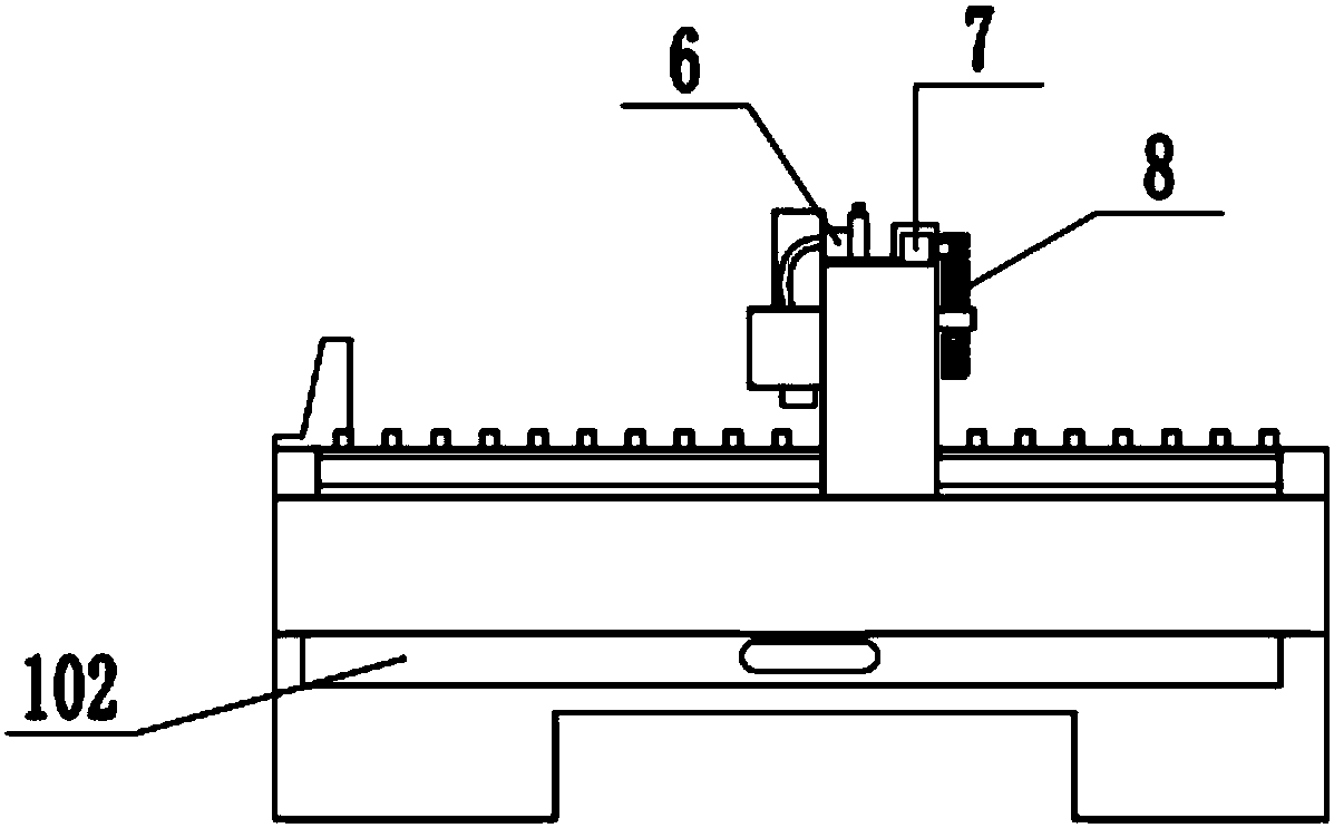
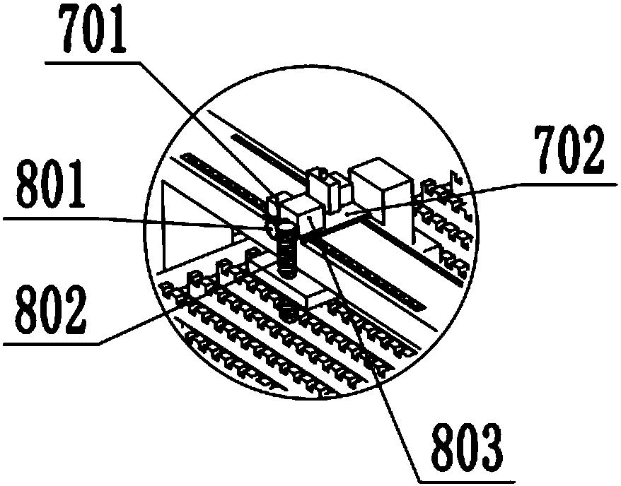
[0030] see Figure 1-6 As shown, a numerically controlled laser cutting device of this embodiment includes a machine base 1, a moving beam 2, a protective device 4, a laser cutting head 5, an exhaust gas treatment device 6, a mobile platform 7, and a lifting device 8, and is characterized in that: The top of the machine base 1 is provided with a moving beam 2, and one side of the moving beam 2 is provided with a laser cutting head 5, and the laser cutting head...


PUM


Abstract

The invention discloses a using method of a numerical control laser cutting device. The numerical control laser cutting device includes a machine base, a moving crossbeam, a guarding device, a laser cutting head, an exhaust gas treatment device, a moving table, and a lifting device. The moving crossbeam is arranged above the machine base. The laser cutting head is arranged on one side of the moving crossbeam. The laser cutting head is provided with the guarding device in a sleeved mode. The guarding device comprises a connecting plate and a guarding cover. One side of the guarding cover is connected with the connecting plate. A laser cutting head trepanning is formed in the upper end of the guarding cover. The laser cutting head is arranged in the laser cutting head trepanning. The upper end surface of the moving crossbeam is provided with a sliding way. The sliding way is provided with a moving table. The moving table is provided with a moving motor. One side of the moving motor is provided with the exhaust gas treatment device and the lifting device. The exhaust gas treatment device is connected with the guarding cover. The lifting device is connected with the connecting plate. One side of the machine base is provided with a controller. The controller is connected with the moving motor and the laser cutting head.

Description

technical field [0001] The invention relates to the field of cutting machines, in particular to a method for using a numerically controlled laser cutting device. Background technique [0002] CNC laser cutting machine is to focus the laser emitted from the laser into a high-power density laser beam through the optical path system. During the cutting process of the current CNC laser cutting machine, the high-intensity light will cause damage to the human eye and at the same time The skin will also be burned to a certain extent, and the toxic gas produced during the cutting process will also cause great harm to the operator's body, and the current method of using the CNC laser cutting device has complicated operating procedures and is not easy for the operator to operate and control. Contents of the invention [0003] The purpose of the present invention is to provide a method for using a numerically controlled laser cutting device to solve the problems raised in the above-m...

Claims


Application Information

Patent Timeline
Patent Type & Authority Applications(China)
IPC IPC(8): B23K26/08B23K26/142B23K26/38
CPCB23K26/0876B23K26/142B23K26/38
Inventor 王余江
Owner 王余江
Learn More