Centralized heating method and system

A technology for central heating and water supply temperature, applied in heating systems, hot water central heating systems, heating methods, etc., can solve the problems of increased operating costs, increased pressure difference between supply and return water, pressure on pipes and equipment, etc. problems, to achieve the effect of reducing transformation investment, reducing operating pressure, and reducing operating costs

Active Publication Date: 2018-05-29
CHANGAN UNIV
View PDF4 Cites 3 Cited by
  • Summary
  • Abstract
  • Description
  • Claims
  • Application Information

AI Technical Summary

Problems solved by technology

However, the method of replacing the heat source circulating water pump has the following disadvantages: 1. The pressure of the water supply pipeline increases, causing problems for the pressure bearing of the pipeline and equipment, which can easily lead to rupture of old equipment and pipe networks, bringing huge economic losses and affecting the supply. heat effect
Second, the pressure difference between the supply and return water of the front-end users close to the heat source increases, which not only increases the throttling loss, but also further deteriorates the hydraulic imbalance of the system, resulting in the heating effect of the front heating and the cooling
3. The investment of replacing the main heat source water pump is high. As the power of the water pump increases, the power supply capacity will also increase accordingly.
Four, high energy consumption
However, the method of setting the relay pumping station has the following disadvantages: First, the setting of the relay pumping station needs to solve the site and power supply problems, which increases the investment
2. The relay pump station is far away from the heat source, and special personnel are required for maintenance and management, which increases operating costs
Third, the relay pump and the heat source circulating water pump form a series relationship, and the pressure conditions affect each other, which brings certain difficulties to the operation adjustment
However, the method of installing a secondary booster pump at the user still has the following disadvantages: First, each user installs a circulating water pump, and the initial investment is relatively high
Second, the pumps work in parallel at the same time, which will cause dynamic hydraulic balance problems
3. The head of the secondary booster pump of the user far away from the heat source is too large, resulting in excessive power of the end user pump

Method used


Image

  • Centralized heating method and system
  • Centralized heating method and system
  • Centralized heating method and system

Examples


Embodiment 1

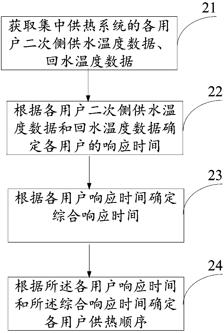
[0072] figure 2 It is a flow chart of the central heating method of the embodiment of the present invention, image 3 (a) in the embodiment of the present invention is a flow chart of the method for determining the heating order of each user, such as figure 2 and image 3 Shown in (a), the present invention provides a kind of central heating method, and described method comprises:

[0073] Step 21: Obtain the secondary side water supply temperature data and return water temperature data of each user in the central heating system.

[0074] Step 22: Determine the response time of each user according to the secondary side water supply temperature data and return water temperature data of each user; the specific steps include:

[0075] According to the water supply temperature data and return water temperature data of each user's secondary side, determine the cooling rate of each user when the heat is stopped;

[0076] Determine the temperature drop value of each user within...

Embodiment 2

[0097] figure 2 It is a flow chart of the central heating method of the embodiment of the present invention, image 3 (b) is a flow chart of the method for determining the heating order of each user in the embodiment of the present invention, such as figure 2 and image 3 Shown in (b) in, the present invention provides a kind of central heating method, described method comprises:

[0098] Step 21: Obtain the secondary side water supply temperature data and return water temperature data of each user of the central heating system;

[0099] Step 22: Determine the response time of each user according to the secondary side water supply temperature data and return water temperature data of each user; the specific steps include:

[0100] According to the water supply temperature data and return water temperature data of each user's secondary side, determine the cooling rate of each user when the heat is stopped;

[0101] Determine the temperature drop value of each user within th...

Embodiment 3

[0124] Figure 4 It is the structural diagram of the central heating system of the embodiment of the present invention, as Figure 4 As shown, the present invention provides a centralized heating system, which includes: an acquisition module 41 , a module 42 for determining the response time of each user, a module 43 for determining the comprehensive response time, and a module 44 for determining the order of heating for each user.

[0125] The acquiring module 41 is configured to acquire secondary side water supply temperature data and return water temperature data of each user in the central heating system.

[0126] Each user response time determination module 42 is used to determine the response time of each user according to the secondary side water supply temperature data and return water temperature data of each user; the each user response time determination module 42 specifically includes:

[0127] The cooling rate determination unit is used to determine the cooling r...


PUM


Abstract

The invention discloses a centralized heating method and system. The method comprises the steps that secondary side water supply temperature data and return water temperature data of users of the centralized heating system are obtained firstly; according to the secondary side water supply temperature data and return water temperature data of the users, response time of the users is determined; comprehensive response time is determined according to the response time of the users; and finally the heating sequence of the users is determined according to the response time of the users and the comprehensive response time. The heating sequence of the users is determined according to the response time of the users, the number of heating users in the same time period is reasonably set, accordingly, centralized heating pipeline operation pressure is reduced, improvement investment is reduced, and the operation cost is reduced.

Description

technical field [0001] The invention relates to the technical field of central heating, in particular to a central heating method and system. Background technique [0002] With the promotion and application of energy-saving technologies, the intensity of heating energy consumption continues to decline, but the total heating energy consumption is also increasing year by year due to the increase in heating area in northern cities and towns. As the heating scale increases, the operating flow of the heating pipe network increases year by year, resulting in an increase in the energy consumption of the heating station. [0003] In the process of heating scale development, the pipe network flow is getting bigger and bigger, the most unfavorable loop is getting longer and longer, and the pressure drop of the pipe network is getting bigger and bigger. In order to meet the needs of increasing central heating load year by year, under the condition that the transformation of the heatin...

Claims


Application Information

Patent Timeline
Patent Type & Authority Applications(China)
IPC IPC(8): F24D3/02F24D19/10
Inventor 江超官燕玲
Owner CHANGAN UNIV
Why Eureka
Try Eureka