
Fiber force value inspection tool

A force value and fiber technology, applied in the direction of tension measurement, can solve the problems of changing the spring compression, inability to accurately measure the fiber tension force value, etc., and achieve the effect of reducing friction, ensuring service life and low processing cost.

Active Publication Date: 2019-12-03
NINGBO WENZE TEXTILE CO LTD
View PDF7 Cites 0 Cited by
  • Summary
  • Abstract
  • Description
  • Claims
  • Application Information

AI Technical Summary

Problems solved by technology

But for the fiber, the change of the tension force is very small, which cannot cause a significant change in the compression of the spring, and cannot effectively reflect the change of the tension value by using the elastic force, so it is impossible to accurately measure the force of the tension force of the fiber. value size

Method used


Image

  • Fiber force value inspection tool

Examples


Embodiment Construction

[0016] The present invention will be described in further detail below by means of specific embodiments:

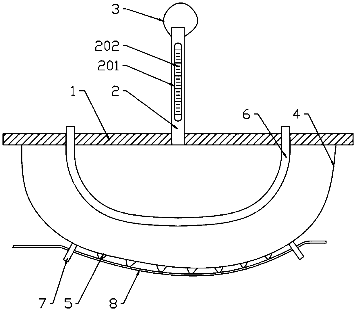
[0017] The reference signs in the accompanying drawings of the description include: mounting plate 1, air pipe 2, visible section 201, scale line 202, expansion air bag 3, compressed air bag 4, ice beads 5, cooling pipe 6, guide plate 7, and fiber 8.

[0018] The embodiment of the fiber force value checker is basically as attached figure 1 Shown: including mounting plate 1, air pipe 2, cooling pipe 6, expansion air bag 3 made of latex and compressed air bag 4 made of plastic film, the outer surface of compressed air bag 4 is coated with a layer of rapeseed oil film, air pipe 2 and The compressed airbags 4 are respectively installed on both sides of the mounting plate 1, and the compressed airbags 4 are filled with gas that keeps the compressed airbags 4 fully bulging. It is a transparent visible section 201, and the visible section 201 is provided with a scale line 202. ...


PUM


Abstract

The invention relates to the field of textiles, and discloses a fiber force value gauge. The fiber force value gauge comprises a mounting plate, an air pipe, a cooling pipe, an inflation air bag madeof latex and a compressed air bag made of a plastic film. The air pipe and the compressed air bag are arranged on both sides of the mounting plate respectively. The compressed air bag is filled with gas which enables the compressed air bag to remain full and plump. One end of the air pipe runs through the mounting plate and is communicated with the compressed air bag. The central part of the air pipe is a transparent visible section, and a piston is slidingly connected with the inside visible section. The inflation air bag is fixed on the other end, which is away from the mounting plate, of the air pipe. The air pipe is communicated with the inflation air bag. A number of adsorption units capable of adsorbing water droplets are arranged on the outer surface of one side, which is away fromthe mounting plate, of the compressed air bag. The cooling pipe is arranged on the mounting plate. The cooling pipe is located in the compressed air bag. The invention provides the fiber force value gauge which can accurately measure the force value of fiber tension force.

Description

technical field [0001] The present invention relates to the textile field. Background technique [0002] The draw frame in textile machinery is a textile machine that combines multiple carded fibers into fibers with certain quality requirements. The function of the drawing frame is to improve the internal structure of the fiber sliver, thereby improving the uniformity of its long segment, and at the same time reducing the weight unevenness, so that the fibers in the fiber sliver are straightened and parallel, and the hooks are reduced. Multiple carded fibers enter the draw frame at the same time to synthesize fiber slivers with certain quality requirements. During the synthesis process, all fibers need to be tensioned to the same tension to ensure the uniformity of long segments of fiber slivers. Therefore, in the process of adjusting the fiber tension, it is necessary to accurately detect the force value of the fiber tension. [0003] The Chinese invention application wit...

Claims


Application Information

Patent Timeline
Patent Type & Authority Patents(China)
IPC IPC(8): G01L5/08
CPCG01L5/08
Inventor 孙文清
Owner NINGBO WENZE TEXTILE CO LTD
Learn More